Showing posts with label #entarch. Show all posts

2019-05-07

Better architecting with - standard viewpoints and model-types

1 Smart Cities Reference Architecture Methodology


The IEC System Committee “Smart Cities” is mandated to develop the Smart Cities Reference Architecture (SCRA) which is a template for various Smart Cities solution architectures.  Although there are many reference architectures for Smart Cities, those architecture have been developed under different and unknown methodologies. This made practically impossible to use them together and to adjust them to the needs of a particular city system.

To address this problem the IEC System Committee “Smart Cities” had decided to develop Smart Cities Reference Architecture Methodology (SCRAM) as an international normative document IEC SRD 63188. The SCRAM provides the logic how to build the SCRA and how to tailor the SCRAM and SCRA. The ability to tailor is very critical.
  • Cities, as places where people live and work, are very important for our civilisation.
  • All cities are different.
  • Smart City is a city which makes the world easier for citizen, society, business and government.
  • In Smart Cities projects 50% – 70% of work is about IT, i.e. digital.
  • Smart City is a city which is rebuilt as a digital system (Digital Transformation is critical).
  • Digital systems can be done well, be adaptable and easy repeated (this is the main secret of Digital Transformation), but such emergent characteristics have to be purposefully created.
  • If a common methodology for building Smart Cities as digital repeatable systems is used, then all Smart Cities are the 70% same (an estimation).
  • Coordinated and cooperated building together Smart Cities as digital repeatable systems leads to substantial gains in cost, speed and quality of their implementations.
  • An export version of the Smart Cities implementation is created automatically.

Considering that Smart Cities will be digital repeatable systems, it has been understood that a platform is necessary. The SCRA outlines the Common Smart Cities Digital Repeatable Platform. Because of the complexity in Smart Cities, this platform is actually a complex of platforms (See the illustration below, which is slightly different from the various version in https://improving-bpm-systems.blogspot.com/2019/03/better-architecting-with-solution.html). For each platform, the SCRA lists its own components and essential capabilities for each component.


To describe such complexity, the SCRAM provides 11 viewpoints and 107 model-kinds. Additional, the Smart Cities Implementation Manual is anticipated for continual improvement and collecting knowledge about the SCRAM and SCRA.

2 Example of tailoring


A country NNN decided to introduce a country-wide ICT reference architecture for all Smart Cities projects. The country wanted to reuse the SCRAM and SCRA for the NNN-ICT RA. There are two fundamental requirements:
  1. The NNN-ICT RA must include communication infrastructure which is not defined in the SCRAM and SCRA.
  2. The NNN-ICT RA must be detailed enough as a Reference solution architecture.

A recommended tailoring is below. For Reference architecture, consider the following:
  • Describe the requirements for NNN-ICT RA by covering the SCRAM model-types 7.2-7.15; maybe in a free format.
  • Outline NNN-ICT RA via the SCRAM model-types 7.16-7.30; use SCRA whenever possible.
  • List of platforms to be provided at the beginning via the SCRAM model-type 7.43.
  • Provide a view of the Universal platform via SCRAM PLATFORM ENGINEERING viewpoint (thus you will know components and solutions for this platform).
  • Provide a view of the Urban Platform via the SCRAM PLATFORM ENGINEERING viewpoint (thus you will know components and solutions for this platform).
  • Provide a view for each vertical platform, e.g. transportation, gas, water, energy, waste etc. via the SCRAM PLATFORM ENGINEERING viewpoint (thus you will know components and solutions for these platforms).
  • For each SCRAM model-types 7.31-7.42 develop implementation materials, i.e. how different teams must provide various information, e.g. model processes, data, etc.
  • Provide any additional views and models, especially for communication infrastructure.

For Reference solution architecture, consider the following:
  • Provide view for the SCRAM CROSSCUTTING ASPECTS ENGINEERING viewpoint.
  • Provide view for the SCRAM RISK MANAGEMENT viewpoint.
  • Provide view for the SCRAM SOFTWARE FACTORY viewpoint.
  • For each component of the Universal platform, provide a view via the SCRAM PLATFORM COMPONENT ENGINEERING viewpoint (start with 7.51-7.53).
  • For each solution on top of the Universal Platform, provide a view via the SCRAM SOLUTION ENGINEERING viewpoint (start with 7.65-7.67).
  • For each component of the Urban platform, provide a view via the SCRAM PLATFORM COMPONENT ENGINEERING viewpoint (start with 7.51-7.53).
  • For each solution on top of the Urban platform, provide a view via the SCRAM SOLUTION ENGINEERING viewpoint (start with 7.65-7.67).
  • For each component of the vertical platform, provide a view via the SCRAM PLATFORM COMPONENT ENGINEERING viewpoint (start with 7.51-7.53).
  • For each solution on top of the vertical platforms, provide a view via the SCRAM SOLUTION ENGINEERING viewpoint (start with 7.65-7.67).
  • Provide any additional views and models.

3 SCRAM viewpoints and model-kinds

3.1 VALUE viewpoint

The value viewpoint describes the problem space in terms of expected value for the stakeholders by providing some ideas about potential overall solutions (called system-solutions to distinguish them from solutions on top of a platform). The value viewpoint comprises the following model-types:
  • Problem space overview (see 7.2)
  • Problem space terminology (see 7.3)
  • Problem space specifics nomenclature (see 7.4)
  • Problem space classifications nomenclature (see 7.5)
  • Stakeholders nomenclature (see 7.6)
  • Stakeholders’ concerns nomenclature (see 7.7)
  • Dependencies between generic system stakeholders, stakeholders, stakeholders’ concerns and categories of concerns (see 7.8)
  • High-level requirements nomenclature (see 7.9)
  • High-level stories nomenclature (see 7.10)
  • High-level use cases nomenclature (see 7.11)
  • Problem space coverage by the high-level use cases (see 7.12)
  • The mission statement (see 7.13)
  • The vision statement (see 7.14)
  • The strategic goals nomenclature (see 7.15)

3.2 BIG PICTURE viewpoint

The big picture viewpoint outlines the solution space and describes potential system-solutions as a set of high-level elements. The big picture viewpoint comprises the following model-types:
  • Solution space boundaries (see 7.16)
  • Solution space terminology (see 7.17)
  • Solution space constraints nomenclature (see 7.18)
  • Solution space classifications nomenclature (see 7.19)
  • Solution space essential emergent characteristics nomenclature (see 7.20)
  • Dependency matrix between problem space essential high-level requirements and solution space constraints vs. solution space essential emergent characteristics (see 7.21)
  • Solution space architecture principles nomenclature (see 7.22)
  • Dependency matrix between solution space essential emergent characteristics vs. solution space architecture principles (see 7.23)
  • High-level illustrative diagrams (see 7.24)
  • High-level business map (see 7.25)
  • Beneficiaries’ journeys nomenclature (see 7.26)
  • High-level reference capability map (see 7.27)
  • High-level process map (see 7.28)
  • High-level architecture (see 7.29)

3.3 SYSTEM-SOLUTION ENGINEERING viewpoint

The system-solution engineering viewpoint describes the system-solution as sets of artefacts such as capabilities, processes, service, functions, data, information, etc. This viewpoint explains how the system-solution delivers value to its beneficiaries as well as how the system-solution actually runs itself. The model-types of the system-solution engineering viewpoint are applied to any potential system-solution as the whole and some of its elements. The engineering viewpoint comprises the following model-types:
  • Capability map (see 7.30)
  • Low-level use cases nomenclature (see 7.31)
  • Function map (see 7.32)
  • Partners nomenclature (see 7.33)
  • Process map (see 7.35)
  • Services nomenclature (see 7.34)
  • Decisions nomenclature (see 7.36)
  • Events nomenclature (see 7.37)
  • Data schemas nomenclature (see 7.38)
  • Information flows nomenclature (see 7.39)
  • Document/content classifications nomenclature (see 7.40)
  • Key performance indicators nomenclature (see 7.41)
  • Reports nomenclature (see 7.42)
  • Standards and norms nomenclature (see 7.43)

3.4 PLATFORM ENGINEERING viewpoint

The platform engineering viewpoint covers a platform. A potential system-solutions may contain more than one platform. The platform viewpoint comprises the following model-types:
  • Platforms nomenclature (see 7.44)
  • Platform overview (see 7.45)
  • Platform terminology (see 7.46)
  • Platform components nomenclature (see 7.47)
  • Platform solutions nomenclature (see 7.48)
  • Platform software factory configuration (see 7.49)
  • Platform governance, management and operations manual (see 7.50)

3.5 PLATFORM COMPONENT ENGINEERING viewpoint

The platform component engineering viewpoint covers a component of a platform. The platform component viewpoint comprises the following model-types:
  • Platform component overview (see 7.51)
  • Platform component terminology (see 7.52)
  • Platform component capability map (see 7.53)
  • Platform component function map (see 7.54)
  • Platform component process map (see 7.55)
  • Platform component business specifications (see 7.56)
  • Platform component information specifications (see 7.57)
  • Platform component application specifications (see 7.58)
  • Platform component data specifications (see 7.59)
  • Platform component infrastructure specifications (see 7.60)
  • Platform component security specifications (see 7.61)
  • Platform component services and APIs nomenclature (see 7.62)
  • Platform component software factory configuration (see 7.63)
  • Platform component management and operations manual (see 7.64)

3.6 SOLUTION ENGINEERING viewpoint

The solution engineering viewpoint covers various artefacts of the particular solution. The solution engineering viewpoint comprises the following model-types:
  • Solution overview (see 7.65)
  • Solution terminology (see 7.66)
  • Solution capability map (see 7.67)
  • Solution function map (see 7.68)
  • Solution process map (see 7.69)
  • Solution business specifications (see 7.70)
  • Solution information specifications (see 7.71)
  • Solution application specifications (see 7.72)
  • Solution data specifications (see 7.73)
  • Solution infrastructure specifications (see 7.74)
  • Solution security specifications (see 7.75)
  • Solution services and APIs nomenclature (see 7.76)
  • Solution software factory configuration (see 7.77)
  • Solution management and operations manual (see 7.78)

3.7 CROSSCUTTING ASPECTS ENGINEERING viewpoint

The crosscutting aspects engineering viewpoint specifies engineering practices for several essential emergent characteristics of the system-solution. The crosscutting aspects viewpoint comprises the following model-types:
  • Interoperability aspect (see 7.79)
  • Security aspect (see 7.80)
  • Privacy aspect (see 7.81)
  • Safety aspect (see 7.82)
  • Reliability and resilience aspect (see 7.83)
  • Low cost of operations and time-to-market aspect (see 7.84)
  • Self-reference aspect (see 7.85)

3.8 CORPORATE viewpoint

The corporate viewpoint specifies various governance and management setup of the system-solution. The corporate viewpoint comprises the following model-types:
  • Organisational structure (see 7.86)
  • Governance structure (see 7.87)
  • Project management (see 7.88)
  • Corporate manual (see 7.89)
  • Independent evaluation (see 7.90)
  • Ethics, integrity and ani-corruption (see 7.91)
  • Environment and health (see 7.92)

3.9 RISK MANAGEMENT viewpoint

The risk management viewpoint specifies necessary governance practices. The risk management viewpoint comprises the following model-types:
  • Risk management aspect (see 7.93)
  • Compliance management aspect (see 7.94)
  • Regulatory management aspect (see 7.95)
  • Crime prevention and detection (see 7.96)
  • Auditing (see 7.97)
  • Independent investigation (see 7.98)
  • Crisis management (see 7.99)

3.10 SOFTWARE FACTORY viewpoint

The software factory viewpoint specifies BizDevOps practices. The whole logic of the software factory is quickly create a simple but complete solution, validate it and gradually enrich it. The implementation viewpoint comprises the following model-types:
  • Software factory overview (see 7.100)
  • Prototyping practices (see 7.101)
  • Engineering practices (see 7.102)
  • Assembling practices (see 7.103)
  • Testing practices (see 7.104)
  • Deployment practices (see 7.105)
  • Monitoring practices (see 7.106)

3.11 STANDARDS viewpoint

The standards viewpoint specifies existing and future standards applicable for the system-solution. This viewpoint comprises the following model-types:
  • Existing standards nomenclature (see 7.107)
  • Potential standards nomenclature (see 7.108)

4 Conclusion

The logic behind the SCRAM and its viewpoints/model-types may be used for other digital domains, such as: Digital Healthcare, Smart Homes, Smart Building, argotech, fintech, edutech, etc.

Thanks,
AS


This blogpost belongs to the series https://improving-bpm-systems.blogspot.com/search/label/%23BAW

2019-03-31

Better architecting with - explicit #security

1 Addressing crosscutting aspects by-design


Various crosscutting aspects (also known as non-functional or quality characteristics) of systems are, actually, dependant on all the system elements and relationships between them. For example, the security design principle “weakest link” is saying that “in designing security for a system, focus should be put on the weakest components of the overall system” (see Goldratt E.M., Cox J. The Goal: A Process of Ongoing Improvement, Second Revised Edition, 1992).

The understanding of emergent nature of crosscutting aspects led to raising of requirements for addressing them “by-design”. The most noticeable example of “privacy by-design” is the General Data Protection Regulations (GDPR) from the European Union (see https://eur-lex.europa.eu/eli/reg/2016/679/oj ). The concept “a system characteristic by-design” may be defined as “taking into account the characteristic throughout the system entire lifecycle processes (e.g. architecting, engineering, construction, operating, etc.) as an essential emergent characteristic of the system”.

2 Security Risk Architecture Model (SRAM)


To “estimate” a relative value of a non-functional or quality characteristic of a system at any stage of the system life cycle, it is necessary to “spread” such characteristic over the system elements and relationships between them. Figure below shows, that by knowing:
  1. the security-related paraments, i.e. threats, attacks and vulnerabilities (see oval “Security”) for each least granular system elements;
  2. relationships between the system elements (see oval “Architecture”), i.e.
    • how a set of least granular elements forms a service,
    • how services are used in business processes,
    • how business processes contribute into results,
    • how results reflect goals,
    • how goals are important for the system;
  3. adverse impact which is produced by problems with each system element;
it is possible to objectively evaluate system risks (see oval “Risk management”).


Considering that relationships between system elements are static or dynamic then the structure and behaviour of security will be covered. The same can be done for all crosscutting aspects: security, privacy, safety, reliability, resilience, performance, value, income, expenses and other emergent characteristics.

3 Enhancement practices


There are internal and external enhancement practices for each crosscutting aspect. The internal enhancements practices comprise various certifications and industry agreements which are aspect-specific and element-specific. The external enhancement practices depend on the treatment of an element as:

  • “white-box” with fully internal visibility and testability – some simulation, inspection and compliance external enhancement methods can be used;
  • “black-box” with no internal visibility and testability – use external enhancement points for data/information inputs and outputs, and external enhancement controls for leaks detection;
  • “grey-box” with partial internal visibility and testability – combining two previous options.


Typically, external enhancement methods are based on explicit relationships between elements (e.g. information flows). External enhancement points are based on digital archives and technologies similar to Security Information and Event Management (SIEM) tools. External enhancement controls are monitoring tools with some AI logic, for example, Data Loss Protection (DLP) tools.

For each relationship between elements, use external enhancement points for data/information flow starts and ends, and external enhancement controls for data/information transit.

The static relationships are expressed by any structural connection between elements, but dynamic relationships are expressed only by events (ECA and EPN techniques), processes (BPM techniques) and information flows (IFD techniques).

For example, a process model formally identifies all necessary enterprise enhancement points, methods and controls. (see figure below)
  1. Add all external enhancement points.
  2. Add all external enhancement controls for 4 activities which are “black-boxes”.
  3. Add all external enhancement methods for 2 activities which are “white-boxes” and the process as the whole.
  4. Add all the events and mitigation processes for some of them.


Thus, an explicit description of system elements and relationships between them provides a nomenclature of external enhancement practices, controls, points, and methods to be added to the system. Then they have to be linked to the risk management practices. All the information risk-related information sourced from various crosscutting aspects must be collected and treated together (see figure below).

  1. Enterprise business functions should be enriched to generate the risk-related information.
  2. Those risk-related data need to be collected at the enterprise data warehouse together with other business information.
  3. Some business processes need to be updated to embed risk-related activities.
  4. A set of risk-related rules, logic and risk-related knowledge should be able to use the risk-related and other business data to detect acceptable limits of risk as well as interdependencies and correlations between different risks.
  5. Some business processes for risk mitigation maybe automatically activated.
  6. A lot of risk-related indicators, alerts should be available in the form of dashboards and reports available for different staff members.
  7. Staff members should be able to initiate business processes based on the observed risk-related information.

Additional security-related techniques are mentioned in https://improving-bpm-systems.blogspot.com/2014/04/ideas-for-bpmshift-delenda-est-vendor.html


4 Conclusion


Crosscutting aspects are desired emergent characteristics of a system. They must be addressed systemically.

Thanks,

AS


This blogpost belongs to the series https://improving-bpm-systems.blogspot.com/search/label/%23BAW

2018-06-28

Architecting modern digital systems #entarch #bizarch #apparch #bpm #security #microservice

Mini-course at VFU

1 Title


Architecting modern digital systems

2 The problem to be addressed


At present, there are many IT-related methodologies, technologies, tools and schools of thoughts which overlap and contradict each other. The best practices are actually the best only in particular situations. Often decisions about software-intensive solutions are taken on the in-complete and subjective base. All of this tremendously complicates the modern digital systems thus reducing their potential effectiveness and efficiency. 

3 Objectives


The purpose of this course is to provide the basic knowledge and experience necessary to better understand how to deal with the increasing complexity of the information technologies to obtain the synergy between business needs and IT potentials. 

4 The approach


The course is based on the practical use of Enterprise Architecture (EA) which a methodology and practice for architecting solutions. EA provides an overarching guideline for understanding a “problem space” and take necessary decision about the “solution space” to deliver which addresses the problem. 

5 Learning outcomes


The trainees will
  • learn a systematic approach for architecting digital solutions; 
  • learn about some modern information technologies; 
  • learn how those technologies are working together for a systematic architecting, design, implementation, operations and evolution of digital systems; 
  • carry out a practical architecting exercise. 

6 Target audience


Bachelor and master level students specialising in IT. 

7 Requested knowledge


General knowledge of IS/IT. General programming experience. 

8 Layout of the teaching


Teaching will be given as six 1.5-hour lectures. The first 4 lectures will be about presenting some methodologies and technologies. Then the students will be asked to architect a solution based on a practical situation. The last session will be about presenting the student’s solution and wrapping up this mini-course. 
Thanks,
AS

2018-04-28

Better architecting with – digital models

1 The expression “all models are wrong” is wrong


"All models are wrong" is a well-known aphorism from statistics (attributed statistician to George Box, 1976), which has been used in other disciplines. A modern book on system engineering claims that "The map is not the territory, the menu can’t be eaten, the drawings do not fly, the source code does not store the values of its variables during execution". Let's analyse these statements.

The territory existed before its map. A map is an informational (or digital right now) "twin" of the territory. Since the territory is a natural (made by nature) object, its digital "twin" (made by man) is secondary and approximative.

The menu is the chef's plan and, at the same time, the informational (or digital right now) "twin" of kitchen services. Kitchen services are planned ahead for the several good reasons: discuss them with all the involved persons, organize work, optimize costs and reduce risks. Thus the menu (as a planning tool) helps in achieving the result, but it is not mandatory to provide services. In this case, the informational (or digital right now) "twin" may appear before the physical "twin".

It is clear that the drawings do not fly, but there is no flight without them. Those drawings is a necessary "part" of the aircraft to be manufactured according to these drawings. It is clear that the drawings, in themselves, are not a sufficient "part" of the aircraft because there is a long way from the drawing to the working copy. However, we can consider that the drawings are informational (or digital right now) "ancestors" of aircrafts. In this case, the informational (or digital right now) "twin" is necessarily created before its physical "twin".

Well, finally, the computer program and its source code. What is the relationship between them? There is no program without its source code. The source code can be expressed in several views - in high-level language and in the language of machine instructions (i.e. assembler). This is common but not necessary, because the source code can be interpreted directly without being translated into machine instructions. Wait, this looks rather familiar.

Wow, this is the genetic code for a bionic program! The genetic code does not have all the details, but it determines (albeit partially) the future bionic system. Of course, any bionic system is an adaptive system with a complex "bootstrap" procedure. While modern software systems must be highly-dependable.

So, in ther digital world we copy the mother nature – we create a piece of digital genetic code (in some programming languages) and from it we create a program with the help of the digital environment. Thus, the source code is the main part of the program. Both they are digital artefacts. In this case, there is only an informational (or digital right now) "twin". Well then, it is not a "twin" but an "original"! And this is a digital model.


Physical form
Digital form
Primarily
1. Territory
2. Menu (probably)
3. Drawings (mandatory)
4. Program (inevitable)
Secondarily
2. Meal
3 Plane
1. Map


2 Obliterating differences between architecture and its description in the digital world


For the digital world, we must slightly adjust some of the provisions of ISO/IEC/IEEE 42010 Systems and software engineering - Architecture description. This standard clearly separates the architecture of the system and the description of the architecture. In accordance with this standard, the architecture description consists of models. But in the digital world, models can be also elements of the system-of-interest.

The usage of digital models:
  1. simplifies the choice of elements and system-of-interest options, 
  2. allows making predictions about the behaviour of the system-of-interest and 
  3. replaces the system-of-interest itself, for example, for training purposes. 

Such digital models are machine-readable and machine-executable. For example, a business process is not only an illustration, but also a piece of the source code of the system-of-interest. This increases the importance of Domain-Specific Languages (DSLs) through which some elements of the system-of-interest can be defined in business terms. For example, BPMN is a DSL. (As many years ago with the advent of SGML and HTML people began to say: the program becomes a document, in a document becomes a program.) Also, the appearance of the machine-executed elements of the system-of-interest in the early stages of its life cycle allows us to speak about the emergence of the BizDevOps culture as a natural up-stream extension of the DevOps culture.

The logic of the architecture viewpoints changes. Now, they are designed to systematically create model-types, some of which will be digital, i.e. machine-executable elements and/or machine-readable elements (or nomenclatures, for example, a list of all roles). Architecture viewpoints become some kind of aqueduct columns that support the logic of creating digital systems.


Fragment of the longest (132 km) Roman aqueduct, Tunisia.
(by the way, some parts of this structure are still working and used by local people)

Relationships between models also change. Previously, it was considered that models and views were created solely for stakeholders and, often, different models were created by different people thus models must be permanently aligned, e.g. by a chief architect. With the digital models, there is a lot of interest in semi-automatic and automatic creation of some models from already existing models. For example, if there is a functional map of the organization, then you can automatically offer the initial version of the organizational structure.

It is observed that the difference between the system-of-interest and its architecture description is disappearing in two directions:
  • Some elements of the system-of-interest can be used instead of some architecture description models. 
  •  Some architecture description models became the system elements. 

Ideally, the whole system description should be automatically generated from the existing system elements. This reminds us the “literate programming” from prof. Knuth – see https://www-cs-faculty.stanford.edu/~knuth/lp.html

It is clear that for each type of systems some of its digital models are system-forming elements. Imagine a directed and non-cyclic graph of dependencies between nodes as models and let us assign to its edges measure of the complexity of the "transition" between nodes. Then the models from which one can easily create the majority of other models are system-forming models.

All this is partially described in the series https://improving-bpm-systems.blogspot.com/search/label/%23BAW


Thanks,
AS

2018-03-11

Many viewpoints on the concept capability


This blogpost is based on the several recent LI discussions about the concept “capability” (see their URLs at the end of this blogpost).

Those endless discussions only confirm a well-known systemic observation – a complex concept is better understand via its relationships to other concepts. Thus, to define the concept “capability”, it is necessary to define together the several related concepts, such as “function”, “service” and “process”. (Other concepts could be added on demand.)

Another complexity is, again, a well-known systemic observation – different people see the same thing differently. It is called “architecture viewpoint” (like an 3D object may have 3 projections). The many problem with architecture viewpoints is that they must be aligned.

The aim of this article to outline a main (or master) viewpoint which allows to align all other viewpoints. (With special thanks to Michael Poulin for his valuable comments for this article.)


1 Different viewpoints on capability


So far, the several viewpoints on the concept “capability” have been detected.

Demand viewpoint – to achieve our mission and vision we need a system with a particular performance of doing something. Demand-capability is a relative measure of ability of a system (or its element) doing something at a particular level of performance.

This viewpoint is about WHAT and HOW-WELL without any information about WHO, HOW, WHERE, WITH-WHAT-RESOURCES, etc.

Supply viewpoint – we have a system with a particular performance because we made it and deployed some resources. Supply-capability is a proven performance of a system (or its element) doing something.

This viewpoint is about WHAT, HOW-WELL, WHO, HOW, WHERE, etc.

Reference viewpoint – all the systems with a similar purpose (or mission) should be able to do this. Reference-capability is an ability of a system (or its element) doing something.

This viewpoint is about WHAT only. Typically, the reference viewpoint relates to a particular type of business, e.g. banking, rent-a-car, telecom, etc.

2 Let us classify some of the existing approaches


The list below is copied from https://www.dragon1.com/terms/capability-definition to be annotated.

ArchiMate 3.1: A capability represents an ability that an active structure element, such as an organization, person, or system, possesses. AS: It seems that it is the supply viewpoint.

TOGAF 9.1: A capability is an ability that an organization, person, or system possesses. Capabilities are typically expressed in general and high-level terms and typically require a combination of organization, people, processes, and technology to achieve. For example, marketing, customer contact, or outbound telemarketing. AS: It seems that it is the supply viewpoint.

BIZBOK 4.1: A capability is a particular ability or capacity that a business may possess or exchange to achieve a specific purpose or outcome. AS: It seems that it is the reference viewpoint.

Bas van Gils (Strategy Alliance): CAPABILITY = CAPacity x ABILITY. - ABILITY refers to skills and proficiency in a certain area. It should be noted that ability is a relative term: one actor (human, machine, computer) may have higher levels of proficiency than others. The level of ability can be increased due to (formal) training, and practice. - CAPacity refers to the degree to which actors (human, machine, computer) are available to use their skills to achieve a goal. Capacity can be influenced by freeing up / adding resources to the available pool. More information on the Strategy Alliance Website. AS: It seems that it is the supply viewpoint.

Tom Graves (http://weblog.tetradian.com/2013/12/14/definitions-on-capability/ ) RE “Performance is an attribute of a service – not of a capability as such”. AS: It seems that it is the supply viewpoint.

Mark Paauwe (https://www.dragon1.com/terms/capability-definition ) A capability is a set of tasks that a system is potentially able to perform at a certain performance level, but only with the use of required resources. AS: It seems that it is the supply viewpoint.

Michael Poulin (https://organicbusinessdesign.com/agile-business-capability-part-1/ ) - A business capability is an ability of an entity - person or organisation - to create or deliver certain Real world Effect (outcome) in particular business execution context. If the context changes, yesterdays capability can vanish. A fact that you did something yesterday does not mean (itself) that you can do this tomorrow. A capability exists only if there are all needed resources available for the capability realization. No resources - no capabilities; competencies/knowledge/skills are not enough for having the capability. You lose capability if you outsource it. AS: It seems that it is the supply viewpoint.

Richard Hillier - A business capability is the ability to perform a business activity which is recognized as being required for success and which needs to be specifically managed. AS: It seems that it is the supply viewpoint.

So far, there is no demand viewpoint. Why?

3 Where is the demand viewpoint? 

Any demand viewpoint it is dynamic and organisation specific. In any business, “bigger” (with emergent characteristics) capabilities are assembled from “smaller” (available or not yet) capabilities. Because such emergent characteristics are exhibited as the result of interactions of “smaller” capabilities between themselves and with other capabilities then some coordination of such interactions is mandatory.

Note: It is not a bottom-up approach, but a recursive combination of analysis (finding what "smaller" capabilities are necessary) and synthesis (proving that "smaller" capabilities and some coordination between them achieve "bigger" capability). 

Imagine, an enterprise or solutions architect has to implement a particular demand-capability within an organisation (which is, obviously, a system). There are several choices:
  1. Implement this demand-capability within the organisation as a coordination of some other capabilities.
  2. Outsource this demand-capability via Business-to-Business (B2B) partnership and access it in accordance with a contract between two organisations.
  3. Acquire this demand-capability as commodity maybe via a tender.
  4. Ignore this demand-capability by providing some good reasons.

With the option 1 the enterprise architect must chose a set of “smaller” capabilities and a way to coordinate them. The reference viewpoint, if any, may help to find out those “smaller” capabilities. (Of course, some “smaller” capabilities may be not available yet and have to be implemented recursively).

Also, saying that “to implement this capability we will use those two capabilities” is not enough because the way to coordinate those capabilities will affect the performance of this capability. Sure that various estimations of the performance of this future supply-capability may be provided.

Any demand-capability or reference-capability which is implemented by (or within) the organisation is called function. Creating a function implies that several organisational, technical, contractual, resourcing, staffing and other changes must be carried out within the organisation. Function immediately has some performance approximation as supply-capability, i.e. its expected performance is stated. Ideally, the performance of such supply-capability exceeds the requested performance of the related demand-capability. (Sometimes, a gap between them can be huge – remember that we never drive our cars at their maximum speed.)

An illustration of relationships between various concepts is shown below. The left half of this illustration is the reference map of an organisation and the right half of this illustration is the functional map of this organisation. The functional map is smaller then the reference map, because some capabilities were implemented as commodities or via B2B partnership. A formal procedure for moving from “left” to “right” can be produced on demand.
    

Because functions can’t provide a good approximation of its expected performance, organisations uses services – service is an arrangement to access to one or more functions on a contractual basis. (Note: such an access may be within the same organisation as well as between different organisations). Because any service must take into consideration its contract (including SLA) and its expected usage, its performance may be anticipated better than for functions. Creating services also implies some organisational, technical, contractual, resourcing, staffing and other changes.

Nevertheless, neither functions nor services specify explicitly the coordination between “smaller” capabilities thus their estimations of the expected performance is still a guess. So far, only Business Process Management (BPM) allow the organisation to build, run and improve “bigger” capabilities in predictive, transparent and provable manner because process is an explicit, formal, machine-readable and machine-executable coordination. Obviously, one can evaluate (with a high level of confidence) the performance of a “big” supply-capability by knowing the process, its usage and performance of “small” supply-capabilities.

A few notes: Considering that there are many coordination techniques then there are no principal differences between BPM and Adaptive Case Management – see http://improving-bpm-systems.blogspot.bg/2014/03/coordination-techniques-in-bpm.html . BPM is actually a trio: discipline to manage business via processes, software to manage processes themselves (BPM-suite tools) and practice & architecture. Also, orchestration and choreography are variants of coordination.

Some assets and skills are required to operate services and processes. Obviously, assets and skills may be outsourced (or insourced).

Organisational structure depends on the structure of functions (or functional map). (Think about the separation of responsibilities). http://improving-bpm-systems.blogspot.bg/2011/10/enterprise-pattern-structuring-it.html http://improving-bpm-systems.blogspot.bg/2012/01/enterprise-pattern-sito-extended.html


4 Big picture


The overall logic is the following:

  1. Capability The organisation has to be able to do something (because of the mission) with a particular level of performance (because of the vision).
  2. Function Some of needed (demand-)capabilities must be implemented within the organisation. For example, because it is a core-business capability. By definition, a function is already a supply-capability (as a system element of an organisation as a system) and some assets, skills and coordination have to be provided. 
  3. Service Although function is already a supply-capability, the evaluation of its performance is rather approximative. Service allows improving the evaluation of its expected performance by specifying its contractual conditions.
  4. Process For better estimation of the expected performance, processes (actually, BPM) offer an explicit coordination of ”smaller” capabilities.

5    Conclusion

To avoid confusion when talking about capabilities, please, be explicit about what viewpoint(s) you are using. Also, please, define related terminology up-front.

Thanks,
AS

Related LI discussion
https://www.linkedin.com/feed/update/urn:li:activity:6378549782734077952

Other discussions:

https://www.linkedin.com/feed/update/urn:li:activity:6362283960789135360/

https://www.linkedin.com/feed/update/urn:li:activity:6359453010652905473/

https://www.linkedin.com/feed/update/urn:li:activity:6361138196524388352/

https://www.linkedin.com/feed/update/urn:li:activity:6362638314935246848/

https://www.linkedin.com/pulse/process-vs-capability-volker-wippermann

2018-01-15

Better architecting with – explicit #Digital #Systems Life Cycle (DiSyLiCy)

This blogpost continues the "Better Architecting With" series http://improving-bpm-systems.blogspot.bg/search/label/%23BAW


1 About Digital Systems


A digital system is a system which builds life cycles of its primary artefacts on the primacy of explicit, formal, computer-readable and computer-executable presentation of those artefacts (in other words, digital presentation of those artefacts). For example:
  • a house is designed digitally as an “ideal digital house”;
  • this digital form drives 3D printers and robots to build a real house;
  • this real house is equipped by IoT sensors which generate the “real digital house”, and
  • differences between the “ideal digital house” and the “real digital house” is used for maintenance and various improvements.
Digital systems employ the concept of “digital twins” – computerized companions of physical assets that can be used for various purposes. The relationship between digital twins and physical assets is the following:
  • for a man-made object, a digital twin comes first.
  • for a nature-made object, a digital twin comes second.
For more details about digital, please read http://improving-bpm-systems.blogspot.bg/2015/03/entarch-view-on-ditigal.html

Digital systems are uber-complex real-time systems of cyber-physical, socio-technical and classic IT systems with the following characteristics:
  • digital data and information in huge volumes;
  • software-intensive;
  • distributed and decentralized;
  • great influence on our society;
  • ability to interact with the physical world;
  • many essential characteristics which are required by design and by default (e.g. security, safety, privacy and resilience);
  • low cost of operation;
  • short time to market;
  • self-referential (some), and
  • long and complex life cycle.
This document outlines an approach for building digital systems which is based on synergy between:
  1. the project (or work) management practices and 
  2. the digital systems life cycle management practices.
This approach facilitates optimisation of work management practices for digital systems life cycle. For example, if a digital system has two major components (bespoked and COTS) then each of them may have its own work management practice.

Let us consider the following hierarchy:
  1. The type of a system-of-interest defines its DiSyLiCy (as a variant of the generic DiSyLiCy template) of the system-of-interest.
  2. The DiSyLiCy defines the DiSyLiCy management (because each phase of the DiSyLiCy may have its own management practice).
  3. The DiSyLiCy management defines the work planning (overall and per phases) methods.
  4. Work planning defines the work execution management (i.e. project management).
Note: In the context of this document, the concepts “system-of-interest” and “solution” are used interchangeably because a system-of-interest is a solution of a problem.

2 WHY the Digital Systems Life Cycle (DiSyLiCy) is important


We are dealing more and more with digital systems. They are intrinsically complex systems in which software primarily defines of the system as a whole. The recent trends in digital systems show that such systems have the following common characteristics.
  • Such systems are assembled from many distributed elements which are deployed in various computing environments: in-house, in-cloud (SaaS, PaaS), at partners.
  • Elements of such systems have different granularity, e.g. platforms, applications, services and microservices.
  • Elements of such systems have different life cycles, e.g. some elements, especially business-facing, may require changes more often.
  • Elements of such systems have different ownership: FOSS, bespoke, commodity, community, service providers.
  • Elements of such system may be shared with other versions of this system and/or other software-intensive systems.
  • There are many internal and external drivers for changes of those elements, e.g. security threads, natural evolution of their elements, morphing business requirements, continuous improvements.
  • The speed of changes in their elements must fit the required urgency, e.g. time-to-market, levels of the security risks, etc.
  • The trustworthiness (security, safety, resilience, privacy) of their elements becomes very critical in the digital era because even one “weak link” in an assembly may ruin common efforts.
  • The TCO of such systems follows the classic 20/80 ratio – 20 % to build (development and transition phases) a system and 80 % to operate and evolve it. 
Obviously, only concentrating on the development phase of such systems is not enough because such systems, after being in production, must evolve very fast and in many unpredictable ways. Thus all the phases of the whole life cycle are equally important.

Also, a new “non-functional” (or quality) system characteristic, called “variability”, becomes very critical. “Most modern software needs to support increasing amounts of variability, i.e. locations in the software where behaviour can be configured. This trend leads to a situation where the complexity of managing the amount of variability becomes a primary concern that needs to be addressed.” ( http://program-transformation.org/Variability/SoftwareVariabilityManagement ).

3 HOW the Digital Systems Life Cycle (DiSyLiCy) is composed


The assembled nature of software-intensive systems, certainly, complicates their life cycle which must address:
  • the life cycle of each element and 
  • the life cycle of the system as a whole.
It is clear that such systems share some common characteristics with systems-of-systems (making a system from elements without having a direct ownership on them). Thus, the coordination is critical for the seamless transition from one phase to another and for the seamless integration of various elements.

The necessary coordination is achieved by a combination of the following:
  • Architecture which is critical for good, right and successful software-intensive systems.
  • The systems approach providing a transversal systemic description which comprises several views and models. They evolve together during the system life cycle. http://improving-bpm-systems.blogspot.ch/2017/07/better-architecting-with-systems.html
  • Explicit and tailorable generic DiSyLiCy template which is adjustable to unique needs of the system-of-interest. This life cycle recommends to provide various views and models at different phases.
  • Various architectural styles and techniques to optimise DiSyLiCy within phases and beyond phases for the system-of-interest. 
  • Various work management practices for each phase and beyond phases.

4 WHAT is the Digital Systems Life Cycle (DiSyLiCy)


4.1 Overview of the generic DiSyLiCy template


The DiSyLiCy template comprises the following phase:
  1. Methodology (if needed)
  2. Business case phase
  3. Architecting (or elaboration) phase
  4. Construction (or build or implementation) phase which may comprise the following sub-phases:
    • Architecting sub-phase – if necessary
    • Construction sub-phase
    • Transition sub-phase – if necessary
  5. Transition (or deployment) phase
  6. Pilot (or lab) phase – optional
  7. Production (or operating) phase
    • Operations sub-phase
    • Maintenance (or evolution) sub-phase – repetitive
      • Architecting sub-phase – if necessary
      • Construction sub-phase
      • Transition sub-phase
  8. Retiring phase
  9. Decommissioning phase

Without sub-phases, the DiSyLiCy template is depicted in figure below which shows how a software-intensive system become more concrete during its life cycle.

The complexity of the construction phase must correspond the complexity of its software-intensive system. The construction phase may simultaneously be:
  • recursive –- complex system elements must be architected to produce elements which are simple enough to construct;
  • concurrent – some sub-phases may be executed in-parallel (depending on the availability of resources and dependencies between constructed elements). 
This variant of the generic DiSyLiCy template is depicted in figure below. 

Another variant is to decompose a complex system-of-interest during a single architecting phase.


In the same way, the production phase may have several maintenance phases as shown in the figure below.


Practically all the phases may be repetitive if some conditions of their completion have not been met.

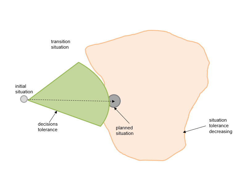
Some phases maybe carried out iteratively (or incrementally) in a few steps to achieve the target situation. Such iterative way of execution is depicted in figures below.

An initial situation

The situation after the first integration.

The situation after the second iteration.

And the final situation.


Please note, that such iterative way of execution is very similar to agile management practices.

4.2 The DiSyLiCy phases vs the systemic description views

At each DiSyLiCy phase, the systemic description of the system-of-interest is updated. in other words, some views (and pertinent models) are prepared and some views (and pertinent models) are updated. The simplified (without sub-phases) dependencies between the DiSyLiCy phases (rows) and the systemic description views (columns) are shown in the table below.


Value
BigPic
Capa
System
Perf
Implem.
Comp.
Test
GMO
Business Case
AGG
AGG
AGG
N/A
N/A
N/A
N/A
N/A
N/A
Architecting
DET
DET
AGG
AGG
AGG
AGG
AGG
N/A
N/A
Constriction
DET
DET
DET
DET
DET
DET
DET
AGG
AGG
Transition
DET
DET
DET
DET
DET
DET
DET
DET
DET
Pilot
DET
DET
DET
DET
DET
UPD
UPD
UPD
UPD
Production
UPD
UPD
UPD
UPD
UPD
UPD
UPD
UPD
UPD
Retiring
N/A
N/A
N/A
N/A
N/A
N/A
UPD
UPD
UPD
Decommissioning
N/A
N/A
N/A
N/A
N/A
N/A
N/A
N/A
UPD
  • AGG – aggregated
  • DET - detailed
  • UPD – updated
  • N/A – not applicable
Naturally, that, during the life cycle, systemic views (and pertinent models) gradually become more and more detailed (or concrete). See the blogpost http://improving-bpm-systems.blogspot.ch/2017/07/better-architecting-with-systems.html for the mapping between views and models.


5   Management of the DiSyLiCy

5.1 General

There are two types of logic in any management practice:
  • specific logic which depends on the life cycle (thus called life cycle management), e.g. what phases to finish or what phases to start, and
  • generic logic which does not depends on the life cycle, e.g. what works to finish and what works to start, depending on various (typical in programme and project management) conditions such as availability of some resources, e.g. free staff. Also called work management.

These two logic are strongly intertwined in the life cycle management. For example:
  • the decision to implement a new system depends on this system’s potential business value and some capacity of some resources (generic logic);
  • the decision to complete the architecting phase depends on the quality of the systemic description (specific logic), and
  • the decision to start in parallel one or more construction phases depends on capacity of some resources (generic logic).

Ideally, the life cycle can be presented as a set of interrelated units-of-work which are managed by these two logics. As said before, each unit-of-work has (minimum) two associated events (the start and the finish) at which these management logics are applied. However, there are a lot of other ad-hoc events at which these two logics must be applied as well. For example, various incidents, capacity fluctuation, etc.

Thus the life cycle management is based on a set of events and the following considerations:
  • there is some natural hierarchy and some coordination between events;
  • some of those events are considered as management points at which some management decisions have to be taken;
  • some management decisions may require different levels of authority;
  • some management decisions may be delegated;
  • any management point is associated with a set of rules based on specific and general logic;
  • some events can be planned (they are also called milestones);
  • some work planning methods are available;
  • missing a milestone is also a management event;
  • if more events are planned and less of them are not missed then the execution of life cycle is more seamless;
  • etc.
Any classic project management is based on the management of work with the use of generic logic only.

5.2 Review of some pertinent management practices


Let us illustrate the life cycle management and work management practices.

PMI is a work management practice which is based exclusively on the generic logic and project life cycle. Obviously, it is mandatory to map the life cycle management of the system to be built into project management life cycle. PMI argues to develop Work Breakdown Structure (WBS) which is a hierarchical decomposition of the total scope of work to be carried out by the project team to accomplish the project objectives and create the required deliverables. Obviously, the WBS is a waterfall-like bridge with life cycle management.

PRINCE2 is a work management practice which is based exclusively on the generic logic and project life cycle (which is more elaborated then from PMI).
Waterfall is a life cycle management practice which executes all its phases sequentially and tries to plan all works in advance. But the usage of the same planning method for all the phases is very inefficient.

Iterative is a life cycle management practice which allows incremental and iterative execution of some its phases.

HERMES is an IT-oriented project management practice which uses a very simplified IT systems life cycle as the project life cycle.

TOGAF is a life cycle management practice which covers, primarily, the implementation of IT solutions. Its Architecture Development Method (ADM) was originally “waterfall-like” but the recently some iterations are admitted.

ITSM is a life cycle management practice for IT services. It provides some planning for related works by outlining all necessary processes.

IT4IT is a life cycle management practice for IT solutions. It is an up-streamed version of the ITSM, however the IT4IT says nothing how to implement IT solutions.

DevOps is a life cycle management practice for IT changes, covering from coding to monitoring.

Agile (SCRUM) is a work management practice with an emphasis on software development. In other word, it is a mixture of life cycle management practice and work management practice, leaning to the latter. It is very light on the solution architecture which is presented as a set of small stories. Thus, creation of work to be done is rather ad-hoc. SCRUM is very strong with the work management by time-bound sprints; it promotes incremental and iterative execution of works. A short-time planning is possible. The SCRUM work management is presented in the figure below.

Case management is a work management practice. The case is a circumstance or undertaking that requires a set of works to obtain an acceptable result or achieve a goal. The case management focuses on the subject, over which the works are performed (for example, a person, a case, an insurance case), and is being led by the gradually emerging circumstances of the case.

Classic process management is a work management practice which formally defines a plan (as a flow-chart) of work. A flow-chart may be mimicking a life cycle. Thus, the planning of work is very explicit.

PDCA is a work management practice for small changes which is carried out in four steps: Plan, Do, Check, Act.

Kanban is a method for work planning (scheduling).

Critical path is a method for work planning (scheduling) for projects and processes.

Table below shows how the 6 management practices are compared to the DiSyLiCy phases. Because some of those practices are enterprise-wide then only pertinent parts of them are considered. For example, only 3 from 4 IT4IT value streams are considered (R2D, R2F, D2C).

PMI
PRINCE2
TOGAF
ITSM
IT4IT
SCRUM
DevOps
Business Case

Fully


Partially


Architecting
Partially
Partially
Fully


Constriction
Fully
Partially
Partially
Partially
Partially
Fully
Fully
Transition
Partially
Partially
Partially
Fully
Partially
Partially
Fully
Pilot

Partially
Partially
Partially

Partially
Partially
Production


Fully
Partially

Partially
Retiring


Partially
Partially


Decommissioning


Partially
Partially


This table shows that no existing management practice which covers fully the DiSyLiCy. 

5.3 Resume

The management of the DiSyLiCy is based on tailoring of the genetic DiSyLiCy template and recommendations what work management practices can be used for each phase.

6 Detailed description ofthe DiSyLiCy phases


Because of this document size only one phase is described below.

6.1 Business case phase

Initiation

An appropriate authority (e.g. a corporate-wide standing Business & IT governance body) mandates an ad-hoc team for this phase to prepare an estimation for a solution of a given problem.
Goal

The goal of this phase is to estimate a solution thus this standing governance committee can take an informed decision “Go / no-Go”.
Deliverables

Typical deliverables of this phase are the following:
  • Solution estimation: initial situation, objectives, scope, assumptions, constraints, schedule, required resources, risks, cost estimation, ROI, etc.
Acceptance practices
The phase team can validate the deliverables with other standing governance bodies, e.g. ARB.

Work management practices


The phase team is composed as the following:
  • business focal point (or Product Owner);
  • business architect or domain business architect;
  • business analyst(s) or domain business analyst(s);
  • solution architect.
Viewpoints and model kinds to be considered

Value view (may be aggregated) with on or many of the following models:
  • Problem space description
  • Problem space influencing factors study
  • The problem space terminology
  • The problem space constrains
  • The mission statement and the vision statement
  • The context (using systems, enabling systems, partner systems) for a future solution (i.e. the system-of-interest)
  • The future solutions’ stakeholder nomenclature
  • Stakeholders’ concerns nomenclature
  • Dependencies between architecture viewpoints, systems roles, stakeholders, stakeholders’ concerns and categories of concerns
  • Some classifications which are specific for the problem space and pertinent for the solution space
  • The high-level requirements (WHO, WHAT, WHY)
  • The high-level stories (WHO, WHAT, WHY, WHERE, WHEN)
  • The high-level use cases (WHO, WHAT, WHY, WHERE, WHEN, HOW)
  • The common high-level requirements
  • The problem space coverage by the high-level use cases
Big picture view (may be aggregated) with on or many of the following models:
  • The solution space terminology
  • The solution space constrains
  • Some classifications which are specific for the solution space
  • Illustrative model(s) of the future solutions including relationships between top-level structure and some context elements
  • The solution space essential characteristics
  • Dependency matrix: problem space common high-level requirements vs. solution space essential characteristics
  • The architecture principles of the solution space
  • The dependency matrix: essential characteristics vs. architecture principles
  • The high-level design for the future solutions
Capability view (may be aggregated) with on or many of the following models:
  • Level 1 capability map
  • Level 2 capability map
  • Level 3 capability map
  • Heat maps
Risk view (may be aggregated)


Thanks,
AS