1 About Digital Systems
- a house is designed digitally as an “ideal digital house”;
- this digital form drives 3D printers and robots to build a real house;
- this real house is equipped by IoT sensors which generate the “real digital house”, and
- differences between the “ideal digital house” and the “real digital house” is used for maintenance and various improvements.
- for a man-made object, a digital twin comes first.
- for a nature-made object, a digital twin comes second.
Digital systems are uber-complex real-time systems of cyber-physical, socio-technical and classic IT systems with the following characteristics:
- digital data and information in huge volumes;
- software-intensive;
- distributed and decentralized;
- great influence on our society;
- ability to interact with the physical world;
- many essential characteristics which are required by design and by default (e.g. security, safety, privacy and resilience);
- low cost of operation;
- short time to market;
- self-referential (some), and
- long and complex life cycle.
- the project (or work) management practices and
- the digital systems life cycle management practices.
Let us consider the following hierarchy:
- The type of a system-of-interest defines its DiSyLiCy (as a variant of the generic DiSyLiCy template) of the system-of-interest.
- The DiSyLiCy defines the DiSyLiCy management (because each phase of the DiSyLiCy may have its own management practice).
- The DiSyLiCy management defines the work planning (overall and per phases) methods.
- Work planning defines the work execution management (i.e. project management).
2 WHY the Digital Systems Life Cycle (DiSyLiCy) is important
We are dealing more and more with digital systems. They are intrinsically complex systems in which software primarily defines of the system as a whole. The recent trends in digital systems show that such systems have the following common characteristics.
- Such systems are assembled from many distributed elements which are deployed in various computing environments: in-house, in-cloud (SaaS, PaaS), at partners.
- Elements of such systems have different granularity, e.g. platforms, applications, services and microservices.
- Elements of such systems have different life cycles, e.g. some elements, especially business-facing, may require changes more often.
- Elements of such systems have different ownership: FOSS, bespoke, commodity, community, service providers.
- Elements of such system may be shared with other versions of this system and/or other software-intensive systems.
- There are many internal and external drivers for changes of those elements, e.g. security threads, natural evolution of their elements, morphing business requirements, continuous improvements.
- The speed of changes in their elements must fit the required urgency, e.g. time-to-market, levels of the security risks, etc.
- The trustworthiness (security, safety, resilience, privacy) of their elements becomes very critical in the digital era because even one “weak link” in an assembly may ruin common efforts.
- The TCO of such systems follows the classic 20/80 ratio – 20 % to build (development and transition phases) a system and 80 % to operate and evolve it.
Also, a new “non-functional” (or quality) system characteristic, called “variability”, becomes very critical. “Most modern software needs to support increasing amounts of variability, i.e. locations in the software where behaviour can be configured. This trend leads to a situation where the complexity of managing the amount of variability becomes a primary concern that needs to be addressed.” ( http://program-transformation.org/Variability/SoftwareVariabilityManagement ).
3 HOW the Digital Systems Life Cycle (DiSyLiCy) is composed
- the life cycle of each element and
- the life cycle of the system as a whole.
The necessary coordination is achieved by a combination of the following:
- Architecture which is critical for good, right and successful software-intensive systems.
- The systems approach providing a transversal systemic description which comprises several views and models. They evolve together during the system life cycle. http://improving-bpm-systems.blogspot.ch/2017/07/better-architecting-with-systems.html
- Explicit and tailorable generic DiSyLiCy template which is adjustable to unique needs of the system-of-interest. This life cycle recommends to provide various views and models at different phases.
- Various architectural styles and techniques to optimise DiSyLiCy within phases and beyond phases for the system-of-interest.
- Various work management practices for each phase and beyond phases.
4 WHAT is the Digital Systems Life Cycle (DiSyLiCy)
4.1 Overview of the generic DiSyLiCy template
The DiSyLiCy template comprises the following phase:
- Methodology (if needed)
- Business case phase
- Architecting (or elaboration) phase
- Construction (or build or implementation) phase which may comprise the following sub-phases:
- Architecting sub-phase – if necessary
- Construction sub-phase
- Transition sub-phase – if necessary
- Transition (or deployment) phase
- Pilot (or lab) phase – optional
- Production (or operating) phase
- Operations sub-phase
- Maintenance (or evolution) sub-phase – repetitive
- Architecting sub-phase – if necessary
- Construction sub-phase
- Transition sub-phase
- Retiring phase
- Decommissioning phase
Without sub-phases, the DiSyLiCy template is depicted in figure below which shows how a software-intensive system become more concrete during its life cycle.
The complexity of the construction phase must correspond the complexity of its software-intensive system. The construction phase may simultaneously be:
- recursive –- complex system elements must be architected to produce elements which are simple enough to construct;
- concurrent – some sub-phases may be executed in-parallel (depending on the availability of resources and dependencies between constructed elements).

Another variant is to decompose a complex system-of-interest during a single architecting phase.

In the same way, the production phase may have several maintenance phases as shown in the figure below.

Practically all the phases may be repetitive if some conditions of their completion have not been met.
Some phases maybe carried out iteratively (or incrementally) in a few steps to achieve the target situation. Such iterative way of execution is depicted in figures below.
An initial situation
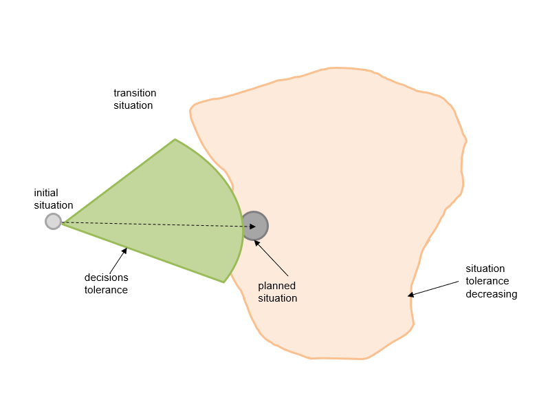 |
The situation after the first integration.
 |
The situation after the second iteration.
 |
And the final situation.
 |
Please note, that such iterative way of execution is very
similar to agile management practices.
4.2 The DiSyLiCy phases vs the systemic description views
At each DiSyLiCy phase, the systemic description of the system-of-interest is updated. in other words, some views (and pertinent models) are prepared and some views (and pertinent models) are updated. The simplified (without sub-phases) dependencies between the DiSyLiCy phases (rows) and the systemic description views (columns) are shown in the table below.
Value
|
BigPic
|
Capa
|
System
|
Perf
|
Implem.
|
Comp.
|
Test
|
GMO
|
|
Business
Case
|
AGG
|
AGG
|
AGG
|
N/A
|
N/A
|
N/A
|
N/A
|
N/A
|
N/A
|
Architecting
|
DET
|
DET
|
AGG
|
AGG
|
AGG
|
AGG
|
AGG
|
N/A
|
N/A
|
Constriction
|
DET
|
DET
|
DET
|
DET
|
DET
|
DET
|
DET
|
AGG
|
AGG
|
Transition
|
DET
|
DET
|
DET
|
DET
|
DET
|
DET
|
DET
|
DET
|
DET
|
Pilot
|
DET
|
DET
|
DET
|
DET
|
DET
|
UPD
|
UPD
|
UPD
|
UPD
|
Production
|
UPD
|
UPD
|
UPD
|
UPD
|
UPD
|
UPD
|
UPD
|
UPD
|
UPD
|
Retiring
|
N/A
|
N/A
|
N/A
|
N/A
|
N/A
|
N/A
|
UPD
|
UPD
|
UPD
|
Decommissioning
|
N/A
|
N/A
|
N/A
|
N/A
|
N/A
|
N/A
|
N/A
|
N/A
|
UPD
|
- AGG – aggregated
- DET - detailed
- UPD – updated
- N/A – not applicable
5 Management of the DiSyLiCy
5.1 General
There are two types of logic in any management practice:- specific logic which depends on the life cycle (thus called life cycle management), e.g. what phases to finish or what phases to start, and
- generic logic which does not depends on the life cycle, e.g. what works to finish and what works to start, depending on various (typical in programme and project management) conditions such as availability of some resources, e.g. free staff. Also called work management.
These two logic are strongly intertwined in the life cycle management. For example:
- the decision to implement a new system depends on this system’s potential business value and some capacity of some resources (generic logic);
- the decision to complete the architecting phase depends on the quality of the systemic description (specific logic), and
- the decision to start in parallel one or more construction phases depends on capacity of some resources (generic logic).
Ideally, the life cycle can be presented as a set of interrelated units-of-work which are managed by these two logics. As said before, each unit-of-work has (minimum) two associated events (the start and the finish) at which these management logics are applied. However, there are a lot of other ad-hoc events at which these two logics must be applied as well. For example, various incidents, capacity fluctuation, etc.
Thus the life cycle management is based on a set of events and the following considerations:
- there is some natural hierarchy and some coordination between events;
- some of those events are considered as management points at which some management decisions have to be taken;
- some management decisions may require different levels of authority;
- some management decisions may be delegated;
- any management point is associated with a set of rules based on specific and general logic;
- some events can be planned (they are also called milestones);
- some work planning methods are available;
- missing a milestone is also a management event;
- if more events are planned and less of them are not missed then the execution of life cycle is more seamless;
- etc.
5.2 Review of some pertinent management practices
Let us illustrate the life cycle management and work management practices.
PMI is a work management practice which is based exclusively on the generic logic and project life cycle. Obviously, it is mandatory to map the life cycle management of the system to be built into project management life cycle. PMI argues to develop Work Breakdown Structure (WBS) which is a hierarchical decomposition of the total scope of work to be carried out by the project team to accomplish the project objectives and create the required deliverables. Obviously, the WBS is a waterfall-like bridge with life cycle management.
PRINCE2 is a work management practice which is based exclusively on the generic logic and project life cycle (which is more elaborated then from PMI).
Waterfall is a life cycle management practice which executes all its phases sequentially and tries to plan all works in advance. But the usage of the same planning method for all the phases is very inefficient.
Iterative is a life cycle management practice which allows incremental and iterative execution of some its phases.
HERMES is an IT-oriented project management practice which uses a very simplified IT systems life cycle as the project life cycle.
TOGAF is a life cycle management practice which covers, primarily, the implementation of IT solutions. Its Architecture Development Method (ADM) was originally “waterfall-like” but the recently some iterations are admitted.
ITSM is a life cycle management practice for IT services. It provides some planning for related works by outlining all necessary processes.
IT4IT is a life cycle management practice for IT solutions. It is an up-streamed version of the ITSM, however the IT4IT says nothing how to implement IT solutions.
DevOps is a life cycle management practice for IT changes, covering from coding to monitoring.
Agile (SCRUM) is a work management practice with an emphasis on software development. In other word, it is a mixture of life cycle management practice and work management practice, leaning to the latter. It is very light on the solution architecture which is presented as a set of small stories. Thus, creation of work to be done is rather ad-hoc. SCRUM is very strong with the work management by time-bound sprints; it promotes incremental and iterative execution of works. A short-time planning is possible. The SCRUM work management is presented in the figure below.

Case management is a work management practice. The case is a circumstance or undertaking that requires a set of works to obtain an acceptable result or achieve a goal. The case management focuses on the subject, over which the works are performed (for example, a person, a case, an insurance case), and is being led by the gradually emerging circumstances of the case.
Classic process management is a work management practice which formally defines a plan (as a flow-chart) of work. A flow-chart may be mimicking a life cycle. Thus, the planning of work is very explicit.
PDCA is a work management practice for small changes which is carried out in four steps: Plan, Do, Check, Act.
Kanban is a method for work planning (scheduling).
Critical path is a method for work planning (scheduling) for projects and processes.
Table below shows how the 6 management practices are compared to the DiSyLiCy phases. Because some of those practices are enterprise-wide then only pertinent parts of them are considered. For example, only 3 from 4 IT4IT value streams are considered (R2D, R2F, D2C).
PMI
|
PRINCE2
|
TOGAF
|
ITSM
|
IT4IT
|
SCRUM
|
DevOps
|
|
Business
Case
|
Fully
|
Partially
|
|||||
Architecting
|
Partially
|
Partially
|
Fully
|
||||
Constriction
|
Fully
|
Partially
|
Partially
|
Partially
|
Partially
|
Fully
|
Fully
|
Transition
|
Partially
|
Partially
|
Partially
|
Fully
|
Partially
|
Partially
|
Fully
|
Pilot
|
Partially
|
Partially
|
Partially
|
Partially
|
Partially
|
||
Production
|
Fully
|
Partially
|
Partially
|
||||
Retiring
|
Partially
|
Partially
|
|||||
Decommissioning
|
Partially
|
Partially
|
5.3 Resume
The management of the DiSyLiCy is based on tailoring of the genetic DiSyLiCy template and recommendations what work management practices can be used for each phase.6 Detailed description ofthe DiSyLiCy phases
Because of this document size only one phase is described below.
6.1 Business case phase
InitiationAn appropriate authority (e.g. a corporate-wide standing Business & IT governance body) mandates an ad-hoc team for this phase to prepare an estimation for a solution of a given problem.
Goal
The goal of this phase is to estimate a solution thus this standing governance committee can take an informed decision “Go / no-Go”.
The goal of this phase is to estimate a solution thus this standing governance committee can take an informed decision “Go / no-Go”.
Deliverables
Typical deliverables of this phase are the following:
Typical deliverables of this phase are the following:
- Solution estimation: initial situation, objectives, scope, assumptions, constraints, schedule, required resources, risks, cost estimation, ROI, etc.
Acceptance practices
The phase team can validate the deliverables with other standing governance bodies, e.g. ARB.
The phase team can validate the deliverables with other standing governance bodies, e.g. ARB.
Work management practices
The phase team is composed as the following:
- business focal point (or Product Owner);
- business architect or domain business architect;
- business analyst(s) or domain business analyst(s);
- solution architect.
Viewpoints and model kinds to be considered
Value view (may be aggregated) with on or many of the following models:
Thanks,
AS
Value view (may be aggregated) with on or many of the following models:
- Problem space description
- Problem space influencing factors study
- The problem space terminology
- The problem space constrains
- The mission statement and the vision statement
- The context (using systems, enabling systems, partner systems) for a future solution (i.e. the system-of-interest)
- The future solutions’ stakeholder nomenclature
- Stakeholders’ concerns nomenclature
- Dependencies between architecture viewpoints, systems roles, stakeholders, stakeholders’ concerns and categories of concerns
- Some classifications which are specific for the problem space and pertinent for the solution space
- The high-level requirements (WHO, WHAT, WHY)
- The high-level stories (WHO, WHAT, WHY, WHERE, WHEN)
- The high-level use cases (WHO, WHAT, WHY, WHERE, WHEN, HOW)
- The common high-level requirements
- The problem space coverage by the high-level use cases
- The solution space terminology
- The solution space constrains
- Some classifications which are specific for the solution space
- Illustrative model(s) of the future solutions including relationships between top-level structure and some context elements
- The solution space essential characteristics
- Dependency matrix: problem space common high-level requirements vs. solution space essential characteristics
- The architecture principles of the solution space
- The dependency matrix: essential characteristics vs. architecture principles
- The high-level design for the future solutions
- Level 1 capability map
- Level 2 capability map
- Level 3 capability map
- Heat maps
Thanks,
AS

