They were used in the following text “Any corporate within the same industry-sector do, in principal, the same things but in slightly different way. If a corporate unified business execution platform enables synergy between uniformity and diversity then the same platform may serve the whole industry-sector (public services, healthcare, smart-city, etc.).”
A few techniques below provide the explanation.
1 Explain the concept platform
An example of platforms: A lot of modern mobile phones, tables, TVs, etc. are built on top of Android platform or iOS platform. Generic characteristics of platforms are:
The platform frees up resource to focus on new opportunities
Successful agile innovations are rapidly scaled up when incorporated into the platform
An agile approach requires coordination at a system level
To minimise duplication of effort in solving the same problems, there needs to be system-wide transparency of agile initiatives
Existing elements of the platform also need periodic challenge
2 Demonstrate to the business that there is a huge opportunity for uniformity
Although each company (in the same industry sector) is unique with its different capabilities, processes, strategy and priorities, there are many similarities (in the same industry sector). Naturally, each business exaggerates the level of diversity.
3 Demonstrate to the IT that an assembly-based solution is better than a monolith solution
A monolith solution is often not good for any Business Unit (BU).
An assembly-based solution is adjustable to needs of each BUs with their own pace.
The assembly-based approach promises re-use and shared services.
4 Demonstrate to the top management that a platform is economically reasonable
To determine whether a platform is economically reasonable or not, one has to estimate the initial cost of the platform, the cost of an application (delivery without the platform), the cost of a solution (delivery with the platform) and the number of expected applications. Figure below demonstrates the financial comparison (Note: the value 8 is an example).
5 Explain to the IT management that the platform will be built incrementally
The level of platform functionality is like as the sea level which absorbs small islands if it is increased.
For each new solution, it will be possible to decide an extent of the usage of the platform. Obviously, the first platform-based solutions will contribute into the platform more than further platform-based solutions.
6 Explain to the governance group how to manage the platform
8 Explain to all the architects that the platform is about coordination of work not data flows
Making flows-of-control explicit and machine-executable is the primary goal of the platform because flows-of-control or “when who is doing what” is fundamental in business. Flows-of-data (and more generic, flow-of-assets), which are popular in SOA and more “visible” by all the architects, can be derived from the flow-of-control.
9 Explain to business architects that each BU will advance with its own pace
Considering that, a platform is intended for all smart-city service providers, but how is it possible to achieve some degree of uniformity among all smart-city service providers if they have different abilities to absorb the benefits of information technologies. Computerisation is a journey, and each smart-city service provider needs to be allowed to adopt a suitable pace for itself, but we also need to maintain coherence in the progression of the whole set. The use of a “ladder” model can be useful since it permits progression of each entity in a stepwise manner but at the same time guides the overall progression in a coherent manner. Design the “ladder” to have a few levels of capability from “not able” to “fully capable”. Entities are permitted to advance at different paces in their ascent to the top of the “ladder”. For example, their progress could be planned as in figure below.
10 Explain to software architects how the platform will be built
The platform is designed to be tools-independent by standardizing data, information, interfaces and coordination between various capabilities. This will allow building the platform incrementally by provisioning needed capabilities from COTS, FOSS, platform-community-owned and in-house components. A few components may be offered for one capability as shown in figure below.
Remember to avoid the use of exotic features of software which is not fully controlled otherwise it will be difficult to replace it.
Evolution of platform is carried out incrementally, continuously and with some verification, in accordance with the classic Deming wheel – Plan, Do, Check, Act
[Plan] how to implement a new improvement as part of a solution
[Do] to implement this solution,
[Check] to validate that this new improvement is valuable at the scale of the platform, and
[Act] to refactor the platforms to incorporate this new improvement and some solutions to use this improvement.
The extent and frequency of these improvements depend on various factors (capability, risk ,etc.). Also, different improvements may have different scopes. And, the implementation of several improvements may overlap in time.
11 Explain to software architects how address versioning of everything
Careful versioning of everything is mandatory! To achieve the versioning of artefacts it is necessary to understand how to treat relationships between artefacts. We recommend that a system be evolved via some kind of transformation cycle as shown in figure below. Start with a stable configuration of approved artefacts. Then introduce a new version of the artefact B3 which is available only for one consumer (i.e. artefact A2) which has to be also versioned. After achieving higher confidence with these new versions, switch all other consumers (i.e. artefact A1) to the new version of the artefact B3. When it is considered that all new artefacts are functioning correctly, their old versions can be removed. The transformation is over and a stable configuration of approved artefacts is once again reached.
Although versioning is mandatory, the use of processes allows to avoid situation in which architects are forced to change all artefacts simultaneously (typical for upgrades and migrations of monolith applications). The changes are process-instance dependent, i.e. already running instances use old versions of some components and newly started process-instances will use new versions of some components. Completion of some process-instances will allow decommissioning of old versions.
Thus architects have the full control over the versioning. Switching for new versions is an independent decision of each application’s owner (i.e. each application may evolve with its own pace).
Solutions architects must be properly train that different solutions architects in similar situations find similar solutions elements or propose innovations.
13 Finally, educate enterprise architects to build-in flexibility
It is mandatory to anticipate changes in the enterprise’s typical artefacts.
All artefacts must be versionable throughout their lifecycle.
All artefacts must evolve to become digital, externalised, virtual and components of clouds.
All relationships between artefacts must be modelled explicitly.
All models must be made to be machine-executable.
Basically, the platform starts from the provisioning capabilities for handling generic artefacts: data structures, documents, events, processes, rules, roles, audit trails, services, processes, etc. Then business reference data/information are managed enterprise-wide. Then core-business data are managed enterprise-wide. Then all the data are transformed into information. At the same time, various services (generic and enterprise-specific) are incorporated into the platform.
14 Explain to industry groups the potentials of platforms
An industry-specific platform can be built in collaboration and coordination between various enterprises – common data schemes, trusted data and documents exchanged, inter-enterprise processes, etc. Enterprises will compete in their core-business innovations but not in re-implementing of their IT systems.
An example of a Corporate Unified Business Execution (CUBE) platform.
This platform is architected from the several components. For each components, a set of capabilities was defined and then best-for-fit COTS products were selected.
This cloud-friendly application architecture opens the way to synergy between #BPM, #SOA, #cloud, #microservices, #IoT, #digital and #security.
2 Clarification of some terminology
2.1 Process
Many articles about microservices mentioned “process”. I believe they mean “computing process” (e.g. an instance of JVM) which should not be confused with “business process”.
O’Reilly book “Migrating to Cloud-Native Application Architectures” http://pivotal.io/platform-as-a-service/migrating-to-cloud-native-application-architectures-ebook says “The ESB becomes the owner of all routing, transformation, policy, security, and other decisions governing the interaction between services. We call this orchestration, analogous to the conductor who determines the course of the music performed by an orchestra during its performance. ESBs and orchestration make for very simple and pleasing architecture diagrams, but their simplicity is deceiving. Often hiding within the ESB is a tangled web of complexity.” I think, this is a wrong analogy. The conductor delivers only one symphony at a time. ESB delivers many symphonies at the same time. Not surprising that it such “centralised orchestration” is difficult.
In other articles, it means one of two BPMN ways to compose business processes – orchestration as a strong coordination and choreography as weak coordination. This orchestration is a domain bounded because it is carried out in the scope of a particular business process.
Microservices communicate with each other through language and platform-agnostic application programming interfaces (APIs). These APIs are typically exposed as Rest endpoints or can be invoked via lightweight messaging protocols such as RabbitMQ. They are loosely coupled with each other avoiding synchronous and blocking-calls whenever possible.”
The first of these two paragraphs says that each microservice is “independent” from other microservices and the second paragraph says “microservices communicate with each other” thus there is some dependency.
Certainly, microservices are interdependent by design and operationally-independent. It seems that microservices may refer to each other indirectly via a “naming service” (some kind of URI to URL mapper or like in CORBA). Therefore, a microservice may employ other microservices to complete its work. In extreme, a microservice may be an assembly of microservices. Article http://microxchg.io/2015/slides/02_01_DomainServiceAggregators.pdf provides an example of data aggregation with a business domain.
Yes, size in LOC does not matter. There is only one limit – SRP. Interesting, that no limitations on “size” of this single responsibility. Thus a microservice with a greater and single responsibility may be assembled from microservices with lesser and single responsibilities.
From https://genehughson.wordpress.com/2015/02/06/wait-did-i-just-say-knuth-was-wrong/ “In the comments, it was suggested that granularity was irrelevant as multiple granular microservices could be composed to form a coarser-grained microservice that would provide a more appropriate level of abstraction. My response was that while this is theoretically true, aggregating service calls in that manner risks issues due to network latency.”
In addition for my comments to that blogpost, I would like to add that designing microservices as distributed autonomous components (each with own computing process) is forcing to consider (up-front and not as refactoring) a proper error-recovery which is much more difficult than the error-handling when components are in the same computing process.
In general, a business capability is a cohesive set of processes (or cluster of processes in accordance with http://improving-bpm-systems.blogspot.ch/2014/03/enterprise-as-system-of-processes.html ). Those processes are implemented as assemblies of microservices. Some of those microservices are unique for a particular process and for a particular cluster; others are shared between clusters.
From https://www.voxxed.com/blog/2015/01/good-microservices-architectures-death-enterprise-service-bus-part-one/ “Microservices and their granularity are ideal for the development and maintenance of the service. But that does push complexity more towards the app itself. A complexity that those apps cannot manage as they are often executed on platform with constrained resources (battery, network, CPU). Combining services in a higher level logic to serve the purpose of apps or business processes proves to be faster to develop and easier to maintain.”
Yes, assembling of microservices is the way to reduce complexity.
If application as a unit of deployment (even decomposed into a few tiers) is no more the physical boundary then boundaries becomes logical and they are coming from the business – business functions, business services and business capabilities. Note they are actually just different viewpoints – see “Common understanding of #bizarch (business architecture) and #BPM” http://improving-bpm-systems.blogspot.ch/2015/01/common-understanding-of-bizarch.html . Less IT applications and more business-process-centric solutions.
From http://nealford.com/memeagora/2015/03/30/architecture_is_abstract_until_operationalized.html “Continuous Delivery and the DevOps movement illustrated the pitfalls of ignoring the effort required to implement an architecture and keep it current. There is nothing wrong with modeling architecture and capturing those efforts, but the implementation is only the first step. Architecture is abstract until operationalized. In other words, you can’t really judge the long-term viability of any architecture until you’ve not only implemented it but also upgraded it. And perhaps even enabled it to withstand unusual occurrences.”
Correct, but slightly simplified observations – actually, 3 (three) major upgrades are necessary to demonstrate that architecture is good. Rationale: it is recommend leaving a solution team before the 3th major upgrade of this solution.
From http://www.infoq.com/articles/service-oriented-architecture-and-legacy-systems “Integration suites offer a complete stack that not only gives ESB capabilities but also more business-specific tools such as BPM (business process management), business activity monitoring, master data management, and a repository.”
As microservices become place-independent, it is necessary to have a good “naming service” (as we had in CORBA) to allow mapping of microservice’s URI to new URL. Such “naming services” is also known as discovery services.
At present, there is no synergy between microservices and API as illustrated by the following quotes:
From http://sdtimes.com/digging-into-microservices/ “The fundamental difference between microservices and APIs is that microservices are used to build applications, whereas APIs are used to integrate applications...”
From http://cloudramblings.me/2015/03/20/microservices-martin-fowler-netscape-componentized-composable-platforms-and-soa-service-oriented-architecture/ “Part of the problem with API management and micro-services or with the mediation / message broker middleware technologies is that these can impose a software layer that is burdensome on the micro-services architecture... Let us say an approach to implementing micro-services would be to put them into a traditional API Management service as offered by a number of vendors. There would indeed be an overhead introduced because the API Layers impose a stiff penalty of authentication, authorization, then load balancing before a message can be delivered. What is needed is a lightweight version of API Management for some trusted services behind a firewall that are low risk and high performance.”
From http://devops.com/blogs/containers-designed-antiquated-application-architecture/ “Cloud-scale applications by nature are stateless with any application state being managed by cache or database services. The compute unit of measure is the process not the CPU, which enables greater scalability. .... They scale across network architectures easily allowing businesses to run in private data centers and leverage cloud for excess capacity when needed.”
From http://12factor.net/backing-services “Twelve-factor processes are stateless and share-nothing. Any data that needs to persist must be stored in a stateful backing service, typically a database.” and “Treat backing services as attached resources”.
one persistency service (or backing service) for the state of the whole solution (even distributed solution)
predefined state which is created by embedding state into an individual containerized copy of the microservice (but the run-time knowledge about the context is mandatory)
idempotency
6.2 Performance
Potential techniques for performance improvement (primarily the network latency):
easy moving an individual containerized copy of the microservice between nodes (thus moving a microservice close to its consumer upto his/her mobile device)
on-demand creating an individual containerized copy of the microservice (but the run-time knowledge about the context is mandatory)
creating an individual containerized copy of the microservice for a particular consumer to diminish the security overhead (but the run-time knowledge about the context is mandatory)
6.3 Lightweight security
predefined state which is created by embedding security keys into an individual containerized copy of the microservice (but the run-time knowledge about the context is mandatory) thus achieving self-containment of PEPs
Let us look at the post “Architecting application architecture #apparch (inspired by #microservices)” http://improving-bpm-systems.blogspot.ch/2014/12/architecting-application-architecture.html and extend the described in it architecture to being cloud-friendly. In that blogpost, I introduced Autonomous Component (AC) with a note that at present, it is not possible to claim that ACs are microservices or services.
This architecture implements business solutions (instead of IT applications because the boundaries of IT applications are not relevant any more) as a coordinated collection of autonomous components. Each AC is a unit of functionality (as SRP) which can be executed in its own computing process (thus a unit of deployment which can be deployed in a separate host somewhere). An AC may be an assembly of several ACs. In general, ACs are structurally interdependent, behaviorally (or operationally) independent and contractually dependent.
Below, several typical ACs are described from the “being cloud-friendly” viewpoint through the following characteristics:
Contracting ACs: Use of some resource-access ACs and short-running ACs.
Example: Web-client or Fat-client for a document management system.
Note: Operation are usually short-running human and short-running automated ones.
Functional role-based portal (FRBP) AC to select a function and execute it with some data/documents as a user-facing AC. It provides two types of operations: 1) static list of functions what this role may do and 2) dynamic list of activities what this role has to do. A function is a set of activities.
Note: There are two types of operations: 1An operation may be short-running human, short-running automated and long-running one. The latter is a coordination of short-running ones and other long-running ones.
Human operation (HO) AC to interact with a human.
Cloud-friendly: stateless or stateful, multiple-place-independent, individual-instantiation.
Security techniques: RBAC, embedded.
Contracting ACs: May use some resource-access, resource-assembly-access and utility ACs.
Example: Interactive form.
Note: The state is kept in a solution-state persistence backing service.
Note: Human operation AC may be short-running and long-running.
Automated operation (AO) AC to transform some resources and/or solution-state data.
The cloud-friendly application architecture is demonstrated on video below to show how various ACs implement a typical process-centric solution (this video is inspired by http://improving-bpm-systems.blogspot.ch/2014/12/bpm-for-soaesbapi-and-cloud-paas-and.html ). Obvious, presented scenario may handle several process-centric solutions and several copies of the same solution (a copy per user) simultaneously.
The scenario has the following stages:
a) The functional-role-based-portal AC offers to a user some functions to initiate (as a static list). Each of functions is an explicit-coordination-operation AC which comprises several human-operation ACs and automated-operation ACs. Human-operations ACs are to be executed by users and they are dynamically listed for each users.
b) All explicit-coordination-operation ACs are implemented as DSL-script. The DSL-manager AC provides a list of functions which are offered for users. The DSL-processor AC provides a list of activities which have to be executed by some users.
c) A user executes a function which is implemented as a DSL-script; the DSL-manager AC instantiates an individual copy of this explicit-coordination-operation AC via the DSL-processor AC. (Covered by markers 1-3.)
d) The first of two operations within this explicit-coordination-operation AC is the automated-operation AC which uses several other ACs; the explicit-coordination-operation AC instantiates an individual copy of this automated-operation AC and individual copies of two of ACs used by it (“Utility” and “Resource assembly access”). Then the automated-operation AC is executed (Covered by markers 4-6.)
e) The second of two operations within this explicit-coordination-operation AC is the human-operation AC; the explicit-coordination-operation AC instantiates an individual copy of this human-operation AC and an individual copy of the other AC used by it. (Covered by marker 7).
f) The human operation AC must be completed by a user and it informs the explicit-coordination-operation AC. (Covered by markers 8 and 9).
g) The explicit-coordination-operation AC terminates.
and its static view
9 Conclusion
The cloud-friendly application architecture follows the business domain boundaries, processes, entities, documents, roles and rules.
The cloud-friendly application architecture reduces complexity by adding a structure among ACs:
long-running functions (actually, business processes)
short-running operations (actually activities or routines)
assembly of resources (actually, business entities or business objects)
resource (actually data and documents)
The cloud-friendly application architecture reinforces the information security by dynamics security for resources and embedded security for ACs
In the cloud-friendly application architecture the majority of ACs are cloud-friendly thus solutions based on this architecture are scalable.
The cloud-friendly application architecture covers majority of cross-cutting concerns : event handling, error recovery, persistence (state management), concurrency, security, interactions, distributed transactions, logging, monitoring and testing.
In the digital age, the focus of enterprise/business/application/etc. architects is not the thing (strategy, policy, service, rule, application, process, etc.) – the focus is how the thing changes and how things change together.
In addition to being cheaper, faster, better it is mandatory to become to more agile, more synergetic (i.e. IoT), more comprehensive.
The goal of IT in the digital age is to be able to provide software-intensive solutions which are easy to evolve instead of classic monolithic applications which are difficult to evolve. This blogpost shows how to design and build process-centric solutions which are easy to evolve. Such solutions are explicit and executable aggregates of components. Aggregates are organised around business processes and components are microservices which wrap various process-related artefacts.
Note: Considering that microservices are autonomous units of functionality, one monolithic application as a big unit of deployment may become a few hundred of microservices as small units of deployment (although the size does not matter in this case).
Both aggregates and components (some of aggregates are components as well) will be analysed from the change (evolution) point of view. In other words, how to carry out changes of each particular artefact and all afterfacts together without breaking the system - enterprise as a systems of processes ( see http://improving-bpm-systems.blogspot.co.uk/2014/03/enterprise-as-system-of-processes.html ) and for achieving the enterprise goals.
Note: Evolution is related to the impact analysis, dependency management and optimisation.
It is considered that all artefacts are versionable and several versions of the same artefact may co-exist in the company’s computing environment. Traceability considerations are at maximum – everything (including changes and work done) is logged as records.
All artefacts are wrapped as services (actually, microservices). A process coordinates (with the use of various coordination techniques – see http://improving-bpm-systems.blogspot.co.uk/2014/03/coordination-techniques-in-bpm.html ) various services and it is a service itself. Thus process is an explicit and executable way to aggregate smaller services into bigger ones. In other words, a process is an aggregated service.
To achieve the versioning of artefacts it is necessary to understand how to treat relationships between artefacts (see 2.4.4 of the book).
We recommend that a system be evolved via some kind of transformation cycle as shown in Figure 1. Start with a stable configuration of approved artefacts. Then introduce a new version of the artefact B3 which is available only for one consumer (i.e. artefact A2) which has to be also versioned. After achieving higher confidence with these new versions, switch all other consumers (i.e. artefact A1) to the new version of the artefact B3. When it is considered that all new artefacts are functioning correctly, their old versions can be removed. The transformation is over and a stable configuration of approved artefacts is once again reached.
Figure 1 Figure 10.3 “Transformation cycle” from the book
In a properly architected system, you may carry out several transformation cycles at the same time.
Process-template and process-instance
A process-centric solution have several processes (actually process-template - a formal description of the process) and some stand-alone services (e.g. a stand-alone service may generate an event which launches one of the processes (actually the process-instance of a process-template - enactment of the process template).
The distinction between process template and process instance is very important. The life-cycle of process-template is controlled at design-time. The life-cycle of process instance is controlled at run-time. A process instance is created, maybe suspended & resumed and finally terminated. Many process instances may co-exist at the same time as shown in Figure 2.
Figure 2 Templates and instances
Process-centric artefacts
Process-centric artefacts and relationships between them are the following:
The business is driven by events
For each event there is a process to be executed
Process coordinates execution of activities (automated and human and sub-processes)
The execution is carried out in accordance with business rules
Each activity operates with some business objects (data structures and documents)
A group of staff member (business role) is responsible for the execution of each human activity
The execution of business processes produces audit trails
Audit trails (which are very detailed) are also used for the calculation of Key Performance Indicators (KPIs)
Also, one can read more about artefacts in chapters 7 and 11 of the book.
Events
Evolution of an event is very straightforward – just new version for any change. Usually, there is a mapping (or decision) table (implemented as a “dispatch” service – see 2.6 of the base blogpost) to provide the correspondence between events and processes. In the simplest policy, a particular event is linked to a particular process template (or a particular version of a particular process template). More sophisticated policies are possible, e.g. usage of the most recent version, time-based selected, etc.
Note: Events mays be generated by processes.
Note: Events may be processed via EPN and decision management techniques.
Potential side-effects (evolving together): None at the moment (just explicitly ignore event if it does not launch any processes).
Process-template
Evolution of a process template is evolution of a composite object. The simplest policy is a very strict binding (also called “early binding”) – a particular version of the process template refers to a particular version of each components (actually microservices).
Figure 3 Early binding
More sophisticated policies are possible, e.g. process-template is using the most recent versions of each component available at the process-instance launching moment (also called “late binding”). Because, the process-template is actually a description then its versioning is not a big problem.
Potential side-effects (evolving together): As life-cycles of a particular process-template and its process-instances do not match, it is necessary to understand what should be done with the running process-instance in case of changing the process-template, although the process-template and its process-instances are different objects (similar to mother and her borne children).
Process-instance
Process-instance is a composite object and its evolution is better to avoid (like changing a running car). Evolution of a process-instance may be necessary for some legal purposes if a long-running process-instance should be modified in accordance with the evolution of related process-template. The related technique is described in http://improving-bpm-systems.blogspot.ch/2010/03/practical-process-patterns-mint.html . Of course, it is better to avoid evolution of process-instance at all, but small changes should be possible.
In practice, the main reason to evolve process-instance is for correcting various errors and exceptions, e.g. in data or in rules or in automation. If some of the components are expected to be quickly evolving or “shaky” then the relationships between the composite and these component should be indirect thus manageable externally.
Figure 4 indirect binding
Sometimes, it is necessary to create a version of an external component which must be used only by a particular process-instance. In general, all external components are re-usable from various aggregates.
Roles
Roles should be define in a suitable DSL externally from the process template and changes for a particular process instance should be possible. Usual technique is to have a set of dedicated functional roles (Responsible, Accountable, Consulted, Informed) for each human activity within a process and be able to provision these roles by various organisational and other roles externally from the process template.
Rules
Rules is a typical service which is implemented in a DSL (decision management notation). This service is stateless and easy to evolve.
Audit trails
Audit trails are easy to evolve. Ii is important to define them explicitly in processes, for example, like measurement-points. Audit trails must be kept outside the process engine in, for example, an enterprise data warehouse thus be independent from evolution of BPM suite itself. Typical process execution data (start/finish time for each activity, etc.) must be merged with some business data to associate separate process-instances which treated the same business objects.
KPIs
If audit trails are done correctly then KPIs are easy to evolve.
Human activity
Human activity is implemented as an interactive service. Sometimes, such a service is a generic tool (which is external to process-template) and such a tool should receive from the process-instance a reference to a human activity to be treated. This is an example of indirect relationship mentioned above.
Sub-processes
Typically, early or late binding is applied for selecting a version of a sub-process to be used (although it depends on capabilities of the business process engine). In the majority of situations, the late binding works fine – just remember to record the version of a sub-process template used in each invocation.
Data structures
As a good practice, business data structures are kept in a generic format (e.g. SDO) and transferred along the process as a black box. To implement some routing logic, additional technical or process-template-specific data structure is created. Bridging between business and technical data structures is done by in automated activities.
Documents
Documents are kept in external repositories, e.g. a document management system or ECM tool. They are referred via URLs and some metadata.
Automated activities
Automates activity is the most “shaky” component of the process (as an aggregate). The indirection binding which is used for them is done through a “robot” (see 2.3 in the base blogpost). Robot is a very stable service and the process-instance passes to it the name of the automation script to be executed as well as input and output parameters. The name of the automation script is a process parameter (thus changeable by the process-template administrator and the process-instance administrator) and input/output parameters are SDOs.
The typical error recovery practice discussed below. Figure 5 shows a “container” in which an automated activity “A” operates within the processes. The normal execution sequence is “E1-A-E2”. Because the automated activity may fail, the container contains the intermediate exception event "E3" and an activity for Error Recovery Procedure (ERP).
In case of failure, the recovery execution sequence will be “E1-E3-ERP-E1-A-A2”. ERP may be very trivial (just try again) or more intellectual (try three times and then ask a person to have a look at it).
In additional to exception, it is necessary to define time-out to prevent endless automated activities as shown in Figure 6.
Figure 6 Error recovery loop and Error Recovery Procedure (ERP) – exception and time-out handling
Automation activity is an automation script which is executed by robot. Typical automation script is an aggregate (usually in an interpreted language) of several micro-services and this aggregate should be executed as a one transaction (see Figure 7).
Figure 7 Execution of an automation script by the robot
Again, normal execution sequence is “E1-A1-A2-A3-E2”. In case of failure of “A2”, the sequence will be “E1-A1-A2-E3-ERP1-E1-A1-A2-A3-E2”. The double execution of “A1” is possible because of that all micro-services are idempotent (see 2.10 in the base blogpost). If “ERP1” is a human activity then the correction of “A” automation script may be carried out within this human activity.
Note: Processes with only automated activities must be idempotent.
Of course, there is no a robot per each automated activity because the robot must be able to handle concurrently several automation scripts as the same time (as several process-instances of the same process-template may be executed at the same time). Instead, there is a queue of jobs for a group of similar robots. An automation activity of a process-instance puts an automation script into a queue and waits for a robot to execute this script and inform the process-instance that this automation activity is completed (see Figure 8).
Figure 8 Queuing of jobs for robots
The queue is shared between various process-instances and it is possible to have several specialised queues. The queue size and robots are monitored.
In some sense, robots work as humans – wait for a job from process-instances, execute jobs when they can and inform a particular process-instance that a particular job is completed.
Conclusion
The describe approach was used (since the year 2000) for a production system comprising about 3 000 complex products per year, 50 persons, about 50 different activities, 3 production chains, 6 repositories and 40 IT services (actually, a couple hundred of micro-services). The system was in place for several years. The maintenance and evolution of this production system required several times less resources. Also, several successful (and easy to do) migrations of its big components were undertaken.
This document is an attempt to outline how BPM (trio: discipline, tools and practices/architecture) can address some concerns of microservices architecture, primarily:
making microservices friendly to clouds (chapter 6)
enhancing information security (chapter 7)
Thus, this document shows a way from monolithic applications to solutions which are based on explicit and executable Coordination Of MicroServices Architecture (COMSA).
Runs in its own process (AS: again, operationally independent, e.g. in its only JVM)
Integrates via well-known interfaces (AS: interface which is implemented language-independent)
Owns its own data storage (AS: a microservice may have its own data storage)
2Implementation techniques for
process-centric solutions
Note, you may want to glance at the chapters 9, 10 and 11 (which provide some information about BPM) before reading this chapter.
2.1Guiding principles
Speed of developing automation is the primary factor of agility of a process-centric solution.
Automation and process template have different speed of changes – keep automation outside the process template.
Automation may be long-running and resource-consuming.
Automation may and will fail.
Failures maybe because of technical (no access to a web service) or business (missing important data) reasons.
Recovery after failure should be easy.
Automation’s problems (failures, resource consuming) must not undermine the performance of process engine.
2.2Interpretive languages
Business routines are usually built on existing APIs to access different enterprise systems and repositories. They look like scripting fragments to manipulate some services and libraries. Thus, a combination of interpreted and compiled static programming languages will bring extra flexibility – interpreted language for “fluid” services (business routines) and compiled language for “stable” services (libraries, business objects, data). Examples of such combinations are: Jython and Java, Groovy and Java, etc. In combining them, it is important to use the strong typing to secure interfaces, enjoy introspection, and avoid exotic features.
Example in Jython: #
# Pending WF # # 2001-09-27 AS: Date written # 2003-04-04 AS: Rewrite # # Pre-processing # def task_Pre_processing( ) : print thisW.getTitle(), "Execute task Pre-processing()" l = thisSession.getResource("/iso/baa/_BO.py") exec(l) BO_initBusinessSession (['pmdb', 'twdb']) ID = thisW.getWorkAttributeAsString(thisWP, "ID") Language = thisW.getWorkAttributeAsString(thisWP, "Language") Languages = thisW.getWorkAttributeAsString(thisWP, "Languages") # # Find related BO # dProjectPmdb = aProjectPmdbHome.findBo ( ID ) if ( not dProjectPmdb.isValid() ) : _PytErrorAdmin("No standard in the PMDB ID=%s %s" % (ID, dProjectPmdb.getReturnMessage())) return pass # Rename workflow title if (thisW.getID() != thisSW.getID() ) : # ? subworkflow ? nameW = thisW.getTitle() nameSW = thisSW.getTitle() thisSW.setTitle(nameSW +" for "+nameW) pass # Display Project's class cc = BO_getProjectClass (dProjectPmdb) thisW.setMasterManager (string.upper(cc[0:1])+string.lower(cc[1:])) ; pass # # Post-processing # def task_Post_processing( ) : print thisW.getTitle(), "Execute task Post-processing()" pass
2.3Robot as a generic microservice
Keeping microservices for “business routines” outside the process description allows some quick modifications even within a running process instance. The execution of such microservices can be carried out by a universal service which receives a reference to a text fragment to be interpreted, fetches this text fragment and interpret it. We call this service “robot”; universal robots and specialised robots may co-exist. Robots must be clonable (for scalability, load-balancing and fault-tolerance).
A crash of a robot will not disturb the process engine except that the activity, which caused the crash, will be marked in the process instance as “late” or “overdue”.
2.4 Monitoring
Ruthless monitoring of all services (including robots, other systems and repositories).
Not just checking that a port is bound, but asking to do a real work; for example, echo-test.
Service should be developed in the way to facilitate such a monitoring.
System should be developed in a way to facilitate such a monitoring.
Also, robots proactively (before executing automation scripts) must check (via monitoring) the availability of services to be used in a particular automation script.
It is better to wait a little than recover from an error.
2.5 Explicit versioning of everything
The intrinsic separation between process template and individual process instance in process-centric solutions allows the use the full power of microservice versioning. A lot of variants are possible:
Process instance may use the “current” version of a particular microservice.
Process instance may use the particular version of a particular microservice.
In case of some compliance requirement:
Since 1st of April all new process instances will use process template v2
Already running process instances must remain at process template v1
Some already running process instances will remain at process template v1 (if those instances are close to the completion)
Some already running process instances may be migrated to process template v2 (if those instances are far from the completion)
Thus everything (process templates, XSD, WSDL, services, namespaces, documents, etc.) must be explicitly versioned and many versions of the “same” should easily co-exist. We also recommend to use the simplest version schema – just sequential numbering: 1, 2, 3, etc.
2.6 Use of other types of coordination in addition to classic process templates
Business rules is another DSL which is very popular in BPM. We recommend to follow the TDM approach ( see http://www.kpiusa.com/ ).
We recommend centralising the treatment of important business events (all external ones and some internal ones) as one service called “dispatch”. The “dispatch” service analyses business events and decides which business process should be initiated. Each process should send to this service an internal business event when the work has been completed (see Figure 1).
Figure 1 “Dispatch” service carries out coordination of processes
Frequently work is divided into three parts (see Figure 2):
pre-processing or preparation, e.g. receipt of information from various sources in different formats, or from different repositories, and conversion into a standard presentation;
doing or processing, i.e. data or information processing in accordance with a standard presentation;
post-processing or finalisation, e.g. conversion from a standard presentation into a particular presentation.
Figure 2 The PDP pattern
Note, the PDP pattern may be used at the scale of the whole processes.
2.8 Pattern AHA (Automated, Human and Automated)
The AHA pattern is a variant of the PDP pattern aimed at facilitating human work, e.g. collection of data and maybe documents for a human activity (in the same way as a good assistant prepares documents for his/her boss) followed by automation of the follow-up activities. We recommend using this pattern to model all intellectual and verification human activities (see Figure 3).
Figure 3 The AHA pattern
Although in some cases the analysis may define that the pre- or post-processing activity is empty, we recommend that these activities are always inserted – in this way the addition of some automation later will be easy because no changes to the process will be required.
2.9 Pattern ERL (Error Recovery Loop)
Any service invoked within a process may fail. The error must be acted upon in some way, e.g. to re-invoke a service, or to suspend or terminate the process. Figure 4shows a possible approach to treat a service failure – here we ask a human to do something to correct the service and then re-invoke the service. In this diagram we consider that the activity Service returns an error flag which is analysed in the gateway G01.
Figure 4 The ERL pattern (with error return)
If the activity Service raises an exception then the diagram should be as shown in Figure 5.
Figure 5 The ERL pattern (with exception). Note, after “Error recovery” activity the execution continues from the end of respective sub-process, i.e. just before the gateway “G01”.
Activity “Error recovery” may be a human activity for a person who is responsible to carry out necessary corrections actions. Depending on the kind of error, this activity may be assigned to different people.
2.10 Pattern IRIS (Integrity Reached via Idempotency of Services)
To achieve integrity within a process, shall we use the ERL pattern “around” each invocation of a service or not? In general yes, but idempotent services can be grouped (as shown in Figure 6). Idempotency of a service means that it can be invoked many times with the same effect. Any state-less service is idempotent. Some state-full services can have this quality also, e.g. a service to add a new version to a document may ignore the request if the most recent version of this document is exactly the same as the requested one.
The process in Figure 6 may have the following audit trail:
Activity01 – finished
Activity02 – failed and raised an exception
Error Recovery – did something
Activity01 – finished again thanks to idempotency
Activity02 – finished
Activity03 – finished
Figure 6 The IRIS pattern. Note, after “Error recovery” activity the execution continues from the end of respective sub-process, i.e. just before the gateway “G01”.
Note, idempotence (pron.: /ˌaɪdɨmˈpoʊtəns/eye-dəm-poh-təns) is the property of certain operations, that can be applied multiple times without changing the result beyond the initial application.
Certainly, I can see a lot of similarities between microservices architecture and process-centric solutions in Figure 8 which is from my book about BPM ( www.samarin.biz/book ), published in the year 2009.
Figure 8 Disassembling monolith into services and assemble them via coordination
The question is how to coordinate separate microservices. The obvious choice is ESB (as shown in Figure 9).
Figure 9 Flow of data
This means that all microservices should be on this picture with potential connectivity everyone to everyone which has the N*(N-1)/2 complexity. Where N is number of microservices resulting in “explosion” of an application. We estimate this number at about 100 per application (or 300 from http://www.infoq.com/interviews/goldberg-microservices).
Where to keep the state for this composite service (i.e. ex-application)? If in ESB then this makes ESB too complicated.
Is ESB cloud-friendly? Just imaging a re-start of the VM with the ESB.
It seems that ESB is necessary but not sufficient. What is missing? We believe that the flow of control is more important than the flow of data (as shown in Figure 10).
Figure 10 Flow of control
In the former, the primary importance is exchange of data. In the latter, the primary importance is the result of working together, but not individual exchanges of data (like in football). Of course, both are necessary, but only ESB is not enough. Considering that more than one coordination techniques may be used by a solution then Figure 11 is more realistic.
Figure 11 Several coordination techniques
The issues (complexity, state and cloud) are answered as following:
Complexity is much lower because only “business routine” services (which are interacting with the process) are depicted.
State is discussed in chapter 4.
Cloud-friendliness is discussed in chapter 6.
Also, some classification of microservices may be added:
explicit coordination (orchestration, cooperation, biz rules, event processing)
functional components (like elementary filters in UNIX pipes)
functional aggregations (e.g. combination of functional components)
data storages
data aggregations (i.e. combination data from several data storages)
human (interactive)
and some combinations of the previous
This classification helps to understand which microservices may be provisioned from clouds.
4 Easy recovering from errors (by design)
We all know that the main difference between a monolithic applications and distributed solutions is in the error recovery practices. We need distributed solutions because of the scalability, fault-tolerance and cloud-based provisioning. At the same time, we have to architect the recovery from losing connectivity between nodes and service failure (VM reloading or note failure).
If a subordinated service (relatively to the coordination service) has failed then the coordination service will recover via error recovery loop (see 2.8 and 2.9).
If the coordination service has failed then some of running its subordinated services cannot complete their associated activities; after the restart of the coordination service, those activities will fail by timeout (because each activity has its SLA).
If a resource may change its state without the control of the process then the process must interrogate the state of such a resource before its usage.
Because of processes which provide clear and detailed context, the identification of problems is very quick.
5 Defining microservices
BPM helps to provide context, define, coordinate microservices. It helps to eliminate endless discussions about the necessary “granularity” of the services:
“If we select a top-down style then we will create coarse-grained business-related services, but we are not sure whether such services are implementable or reusable. If we follow a bottom-up style then we will implement too many fine-grained services for which the business value is not obvious.”
Actually, the native flexibility business processes and explicit versioning allow the rapid and painless adaptation of services to increase or decrease their granularity. Any wrong decisions are easily corrected; services are quickly adapted to the required granularity.
Sure, ESB just a reliable communication mechanism without any business intelligence. Everything is happened in services, even process-centric coordination.
8.5 Decentralized Governance
Sure.
8.6 Decentralized Data Management
Sure again.
8.7 Infrastructure Automation
Yes, also process provides the context for services thus test cases. Process itself is an integration test for its services.
8.8 Design for failure
Sure.
8.9 Evolutionary Design
There are several tempos of design: process, process-specific microservices, common microservices, common operating environment (testing, deployment, monitoring, etc.) and the overall architecture.
Processes make easier to use the power of total versioning. Thus process-specific microservices should mature very quickly.
9 Briefly about Business Process Management (BPM)
BPM (see Figure 12) is a trio: 1) discipline how to better manage an enterprise, 2) COTS and FOSS tools known as BPM suite and 3) an enterprise portfolio of the business processes as well as the practices and tools for governing the design, execution and evolution of this portfolio.
Figure 12 BPM as a trio
The key concept of BPM is business process which is explicitly-defined coordination for guiding the purposeful enactment of business activity flows. In other words, a business process is an agreed plan which is followed each time a defined sequence of activities is carried out; the plan may include some variants and will possibly allow for some unplanned (i.e. unanticipated) changes. (see other BPM-related definitions http://improving-bpm-systems.blogspot.ch/2014/01/definition-of-bpm-and-related-terms.html ).
From the structural (or static) point of view, an enterprise can be presented as a system of processes which comprises various coordination constructs of different granularity (process patterns, processes per se, clusters of processes and value-streams) formed via various coordination techniques (see http://improving-bpm-systems.blogspot.ch/2014/03/enterprise-as-system-of-processes.html ).
For software architects, it is important to know BPM consider business processes explicit (i.e. formally defined to be understandable by different participants) and executable (conceptually, the process instance executes itself, following the BPM practitioner’s model, but unfolding independent of the BPM practitioner; process instances are performed or enacted, which may include automated aspects).
An executable process coordinates the execution of some services. Such a process is expressed in a particular language (i.e. BPMN) and it invokes some services. In Figure 13, the process is in the pool “COOR”, interactive services are in the two pools above it and automated services are in the two pools below it. Note, BPMN is a typical DSL.
Figure 13 Process coordinates some services
This is a classic picture, but how to bring microservices to it?
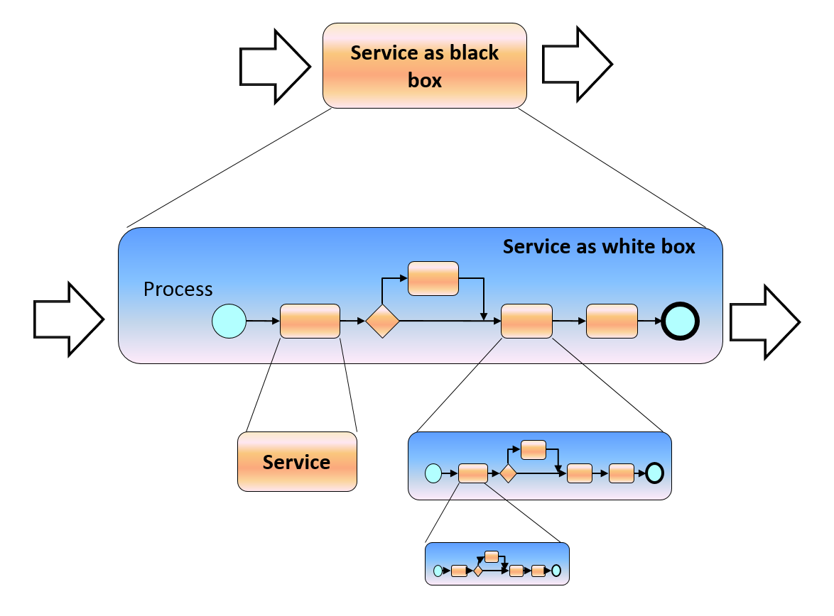
Each enterprise is a complex, dynamic, unique (for each enterprise) and recursive (i.e. like “Russian doll”) relationship (see Figure 14) between services and processes:
All processes are services
Some operations of a service can be implemented as a process
A process includes services in its implementation
Figure 14 Recursive nature of relationship between processes and services
Thus, some “big” services are implemented as explicit and executable processes until only microservices are used.
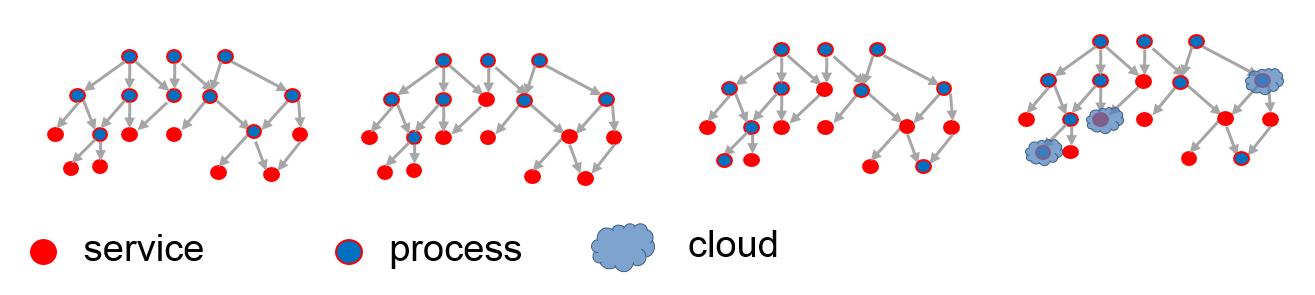
The relationship does not force to have a “pure” structure, but brings flexibility of converting processes to services and vice-versa as necessary, e.g. to use services provisioned from cloud (as shown in Figure 15).
Figure 15 Structure of process and services
Note that the business process modelling procedure should take care about decomposing a big service into smaller services which are coordinated by the process. Different people in similar situations should find similar services (especially, microservices) although that such a decomposition is creative work. Example of such a modelling procedure is in http://improving-bpm-systems.blogspot.ch/2013/07/bpm-for-business-analysist-modelling.html .
11 Multi-layered structuring of process-centric solutions
Because a process coordinates various business artefacts , e.g. “Who (roles) is doing What (business objects), When (coordination of activities), Why (business rules), How (business activities) and with Which Results (performance indicators)”, these artefacts can be structured around processes.
This structure arranges different artefacts on separate layers as shown in Figure 16. Each layer is a level of abstraction of the business and addresses some particular concerns.
Each layer has two roles: it exploits the functionalities of the lower layer, and it serves the higher layer. Each layer has a well-defined interface and its implementation is independent of that of the others. Each layer comprises many services that can be used independently – it is not necessary that all layers be fully implemented at the same time or even be provided in a single project.
Another practical observation is that different layers have lifecycles of different time scales: typical repositories have a 5- to 10-year life-span while the business requires continuous improvement. Because of the implementation independence of the different layers, each layer may evolve at its own pace without being hampered by the others.
Business objects, routines, processes, KPIs, events, rules, audit trails, roles, etc. are the first candidates for microservices which implement particular artefacts.





 Posts
Posts

