Showing posts with label #platform. Show all posts

2018-10-09

MAP for Digital Transformation example – Constructing multiple Smart Cities by an ecosystem of start-ups

Methodology, Architecture and Practice (MAP) for Digital Transformation is a series of blog posts about #DigitalTransformation.

1 Context


At the beginning of October 2018, the www.africup.tn conference took place in Tunisia. The conference was focused on how to help start-ups. Currently, start-ups are the main “source” of jobs in many countries, especially, on the African continent, because traditional companies don’t create new jobs any more.

The conference has been attended by ministers, investors, start-up leaders and other persons and organizations. During the conference, a law for helping start-ups has been adopted (“Loi Startup Act” https://www.ilboursa.com/marches/tunisie-la-loi-startup-act-entre-officiellement-en-vigueur_14957).

The general mood at the conference can be described in the following words: if you can do something right, good and successful for people and countries, there will always be some money for it. Therefore, the conference had a plenary discussion on one of the key problems of Smart Cities of the continent – smart water management. 

2 What is Smart City?


Understanding “a city” as any geographically located population (metropolis, town, village, island, etc.), a Smart City is a city that makes the world easier for citizens, business and government by providing solutions to their problems.

These problems are complex because of their multidisciplinary nature as a mixture of economic, social, technological, legal, environmental and ethical aspects. Solutions to such problems must be aligned and balanced against each other to allow Smart Cities reaching their goals in a sustainable (with preserving stability) manner. 

3 Complexity of Smart Cities


The urban nature of cites naturally leads to a high level of complexity because of the need to control interacting flows of energy, water, waste, transport, food, etc. Each of these flows needs to maintain a balance, to be capable to handle peak loads, to be prepared for quick elimination of consequences of emergency situations (resilience), etc. The figure below shows some of the relationship between the elements of a city. 


Cities are characterized by unpredictable growth, a wide variation in public opinion on priorities, concentration of conflicts and policies.

Each city is unique and all cities have a lot in common.

In the world there are about 4,5 thousand cities with a population of more than 150,000 people.

Construction of a Smart City is not a one-off event but a portfolio of projects with common and evolving purposes.

Making the entire city "smart" cannot be done by a start-up or a mega IT-company (remember General Electric, which tried to make a universal IoT platform alone https://tbri.com/blog/predix-is-looking-for-a-new-owner/ and failed).

Thus, construction of Smart Cities is a systemic problem that can only be solved systemically with
  • involvement of all stakeholders (due to the social orientation of the cities); 
  • proper coordination (for the construction cost of all "Smart Cities"); 
  • broad cooperation (to use the opportunities within the cities), and 
  • digital technologies (for ease of information processing and cloning of digital components). 

4 Systems approach to Smart Cities


In the year 2017, the IEC (www.iec.ch) was created a Systems Committee on Smart Cities. This committee considers a Smart City as a sustainable digital system, which consists of several types of systems: socio-technical, information, cyber-physical, computing, etc.

The usual pattern for defining multiple similar systems is to standardize their reference architecture which will be “adapted” to local conditions by mixing common and specific elements. Based on the reference architecture, various technical committees develop product standards that are used to create various elements. Thanks to the systems approach, such elements form a common and extensible digital platform. At the same time, each Smart City uses its own copy of platform with its own specific elements as shown in figure below.


Knowing that many participants will be involved in construction of Smart Cities, the Systems Committee prepares also a description of the methodology which is used to develop the reference architecture. At present, the Smart Cities Reference Architecture Methodology (SCRAM) is already in the process of consultation (IEC TS 63188 ED1) with countries which participate in the Systems Committee.

The SCRAM helps different people in similar situations to find similar solutions or suggest innovations. Therefore, the use of this methodology and the availability of the reference architecture will enable a particular city to quickly carry out its architectural works and determine that common solutions can be used and what specific solutions to be developed.

The SCRAM also allows to integrate together a lot of existing works for Smart Cities done by ISO, ITU and many other organisations and consortia. 

5 Smart Cities Reference Architecture (SCRA)


The SCRA is built in accordingly with a well-known practice (see ISO / IEC / IEEE 42010): an architecture is described by a consistent set of models that reflects this architecture from different views. Currently, the SCRA uses about 10 views and about 60 models which are defined by the SCRAM. The nomenclature of models and views can be extended because the SCRAM allows to define extra views and extra models as needed. The basic requirement is that all models must be aligned.

It is important that such models describe not only technical aspects, but also reflect social and managerial aspects such as:
  • Public discussion (crowdsourcing). 
  • Public rating (priority and importance). For example, to choose between "important, difficult and long" vs. "maybe relevant, easy and fast”. 
  • A tree of goals for a specific planning cycle. 
  • Unified lifecycle models for various elements. 

The figure below shows one of the models of the SCRA - the first level capabilities. The green marker indicates the water management area.
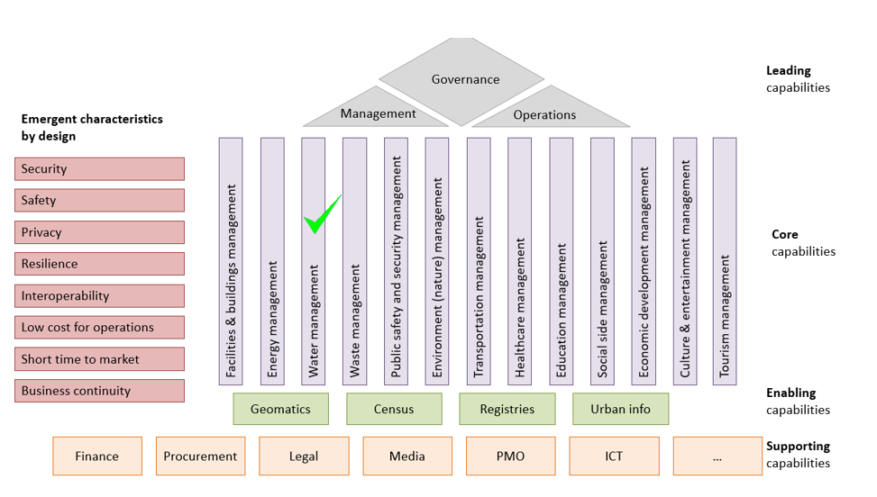


The figure below shows another model that describes the SCRA from a different view as a set of components of a digital platform. Again, a green marker indicates the components that are needed to begin implementing water management.


Note that many of such models are not only a description of the SCRA but also components of the digital platform (see https://improving-bpm-systems.blogspot.com/2018/04/betterarchitecting-with-digital-model. html). Therefore, the SCRA is also part of the reference implementation of Smart Cities. 

6 The implementation of Smart Cities


All the "boxes" in the picture above are functional elements and they are still rather complex. Therefore, additional architectural works are required to decompose a complex functional element into a set of simple functional elements that can be implemented by start-ups. As shown in the figure below, the functional elements (in the left part of the figure) are implemented by start-ups as digital modules (in the right part of the figure) to be used within or on top of the digital platform. Processes for decomposition, supervision and assembly are carried out by the Laboratory of Architectural and Technical Governance (see https://improving-bpm-systems.blogspot.com/2018/09/map/for-digital-transformation.html).


The Laboratory establishes some general rules (including a software factory) and start-ups follow these rules thus forming an ecosystem. Of course, traditional software companies may also participate in such an ecosystem. 

7 Is it a new market?


This modular approach to construct multiple Smart Cities can create a new market for digital modules and services. Any digital module can be financed on the basis of equity participation by investors, the government, start-ups and, even, citizens. The acquisition and use of digital modules by some cities may be organized under various compensation agreements, including “pay as you go”. For such a market, it is possible to introduce its own currency. 

8 Conclusion


Thus a fully transparent and decentralized scheme is formed for the collective construction of solutions for some wicked problems. To launch this scheme, a "place" (in geographically and broader senses) in which a nexus of four following power-streams will happen is necessary:
  • Social (awareness of the situation of a critical mass of society). 
  • Technological (availability of digital solutions and architectures). 
  • Implementational (real construction in "live", materialization). 
  • Financial (transparency who pays, why pays, who benefits) . 

Due to the dynamic nature of this nexus there is no need to theorize endlessly about it and his power-streams - the time for talks is over and some practical work must be started to launch this schema and manage the evolution of this nexus.

Smart Cities is the obvious "place" to launch this schema because a city is the beginning of everything and for everything. At the moment, it seems that Tunisia is, potentially, a geopolitical “place” to launch this scheme with an obvious extension to Africa and the Arab world (and, possibly, the Muslim world).

Note that “Smart Cities” is only an example and such a scheme can be applied for “Digital Healthcare”, “Smart Buildings and Dwellings”, “Smart Manufacturing”, “Digital Legislation” and “Digital Government”.


Thanks,
AS

2017-08-14

Beauty of #microservices - from #DevOps to #BizDevOps via #microservices first

As we all know, usage of MicroService Architecture (MSA) requires the very comprehensive operational practices and infrastructure. A microservice is a unit-of-functionality (or “class” in the informal IT terminology) within its own unit-of-deployment (or “component” in the informal IT terminology) acting as a unit-of-execution (or “computing process” in the informal IT terminology). Some applications may comprise a few hundred of microservices. This is certainly a serious barrier for exploiting MSA benefits such as easy to update and easy to scale to absorb heavy workloads.

Fortunately, as we know, various performance characteristics (e.g. easy to update, easy to scale) are not spread uniformly within applications. For example, 95% of CPU consumption is located in 5% of program code. Thus, it is not necessary to implement the whole application via microservices.

Let us ask a simple question, if a microservice is, actually, a service then can we use microservices and services together? Yes, and some functionality from platforms or monoliths may be used (via API) as well.

Now, let us reformulate the problem. Let us consider that any application is built from many units-of-functionality which must be deployed and then executed. What is the optimal arrangement of units-of-functionality into units-of-deployment and then units-of-execution? In other words,
  • which units-of-functionality have to be implemented as microservices (microservices are agile and good for easy to update, but have some execution and management overhead);
  • which units-of-functionality have to be implemented as monoliths (monoliths are not agile and not easy to update, but have no execution and management overhead);
  • which units-of-functionality have to be implemented as services (classic services are something in between microservices and monoliths).
Thus, a few recommendations may be formulated.
  • Units-of-functionality which are “often” updates must be implemented as microservices (so BizDevOps will be happy).
  • Units-of-functionality which require to absorb heavy workloads must be implemented as microservices (so DevOps will be happy).
  • Units-of-functionally which are “rarely” updated may be packed in a few units-of-deployment (different “packing” criteria may be used) and each unit-of-deployment has its own computing process (so DevOps will be happy). Another option is dynamic loading of those units-of-functionality.
  • Units-of-functionality which are “never” updated may be packed as a monolith or platform, i.e. one unit-of-deployment and one unit-of-execution (so DevOps will be extremely happy).
Applying these recommendations to some phases of the whole application life cycle (conception, development, deployment, production, support, retirement and destruction) the following recommendations may be formulated:
  • At the beginning of the application life cycle (concept, i.e. prototyping, and initial development), the majority of the units-of-functionality must be implemented as microservices, because easy to update characteristic is very important (especially for the business people) and, fortunately, performance characteristics are not an issue. 
  • More close to the end of the development phase, it becomes clear which units-of-functionality have to changed more often than others; so those others may be considered as services and even monoliths or platforms.
  • Also, the load tests (during the development and deployment phases) must show which units-of-functionality will require to absorb heavy workloads thus to be implemented as microservices.
  • Other criteria may be considered as risk, security, etc. 

Obviously, that “moving” a unit-functionality from microservice-like implementation to service-like implementation and to platform-like implementation is much easier that “moving” a unit-of-functionality from monolith-like implementation to service-like implementation and to microservice-like implementation.

This confirms the primacy of the “microservices first” approach. This approach, actually, provides support for BizDevOps practices ( see http://improving-bpm-systems.blogspot.ch/2017/05/beauty-of-microservices-ebanliing.html ). Additionally, this approach enables interesting transformations such as automatic reconfiguration of applications to absorb the heavy workloads by moving temporarily some units-of-functionality from service-like implementation to microservice-like implementation.

Remember from prof. Knuth "Premature optimisation is the root of all evil".

Thanks,
AS

The collection of posts about microservices - http://improving-bpm-systems.blogspot.ch/search/label/%23microservice 

2017-05-31

Beauty of #microservices - making them practical

The classic definition of the microservice architectural style “as an approach to developing a single application as a suite of small services, each running in its own process and communicating with lightweight mechanism” creates a lot of fears and misunderstandings:
  • Application monoliths are evils, but having too many microservices sounds like creating an (unknown) evil as well.
  • Everything has to be re-developed.
  • Microservices will create a huge backlog for our agile team.
  • Microservices? They are neither architecture nor architectural style – just a technical stack.
As usual in IT, any new technology or methodology (which pretends to revolutionized everything) must be used together with many existing ones. Let us “intermix” MSA with some existing and proven technologies and methodologies.

MicroService Architecture (MSA) bring two major concepts:
  1. microservice as a unit-of-functionality, unit-of-deployment and unit-of execution with the same boundaries, and
  2. assembling a whole application from microservices of different origins: off-the-shelf (commercial and FOSS), brought, rented, built, provided from SaaS, PaaS, APaaS, etc.
Using these two concepts, let us try to find a practical balance between monolith architecture and MSA.

Firstly, it is necessary to think about any application as a set of the following artefacts
  • Events
  • Roles (actually, access rights management)
  • Rules (or decisions)
  • Business objects – data structures
  • Business objects – documents
  • Human activities (or screens or interactive services)
  • Automation activities (or scripting fragments or automation services)
  • Coordination
  • Audit trails
  • KPIs
  • Reports
Secondly, consider that each artefact must be, ideally, handled
  • Explicitly
  • As a set of microservices
  • Via APIs
  • With versioning 
  • By a specialized OTS tool, e.g. data structures are handled by a database, processes are handled by a BPM-suite tool
  • In a Domain Specific Language (DSL), e.g. BPMN for processes, DMN for rules
  • Over its whole life cycle
Thirdly, understand specialised tools for that each artefacts:
  • Coordination as explicit and machine-executable processes via a BPM-suite tool
  • Roles via an access management tool
  • Documents via an ECM product
  • Automation fragments as scripts in an interpretive language and execution robots
  • Audit trail and reports via BI tools
  • etc.
Fourthly, prepare two common “pool” for future tools, services and microservices:
  • technological pool for generic off-the-shelf products; their functionality is available via APIs
  • enabling pool for services, microservices, tools which are a) specific for the particular organisation and b) potentially reusable within organisation; their functionality is available via APIs
For each monolith application, sort its functionality out into 2 common pools and an individual pool.


At the result, we got a corporate unified business execution platform which standardise and simplify core elements of the corporate-wide computing system. For any elements outside the platform, new opportunities should be explored using agile principles. These twin approaches should be mutually reinforcing:
  • The platform frees up resource to focus on new opportunities while successful agile innovations are rapidly scaled up when incorporated into the platform.
  • An agile approach requires coordination at a system level.
  • To minimise duplication of effort in solving the same problems, there needs to be system-wide transparency of agile initiatives.
  • Existing elements of the platform also need periodic challenge. Transparency, publishing feedback and the results of experiments openly, will help to keep the pressure on the platform for continual improvement as well as short-term cost savings.
Obviously, do not forget to the a good application architecture - http://improving-bpm-systems.blogspot.ch/2017/05/beauty-of-microservices-ebanliing.html and http://improving-bpm-systems.blogspot.ch/2016/08/better-application-architecture-apparch.html


Thanks,
AS

Other blogposts about microservices - http://improving-bpm-systems.blogspot.ch/search/label/%23microservices

2016-07-01

Electronic Health Records ( #EHR ) implementation with #blockchain, #BPM, #ECM and #platform

This blogpost is an updated version of the chapter 3 from “Technology enabled healthcare transformation” ( see http://improving-bpm-systems.blogspot.ch/2014/07/technology-enabled-healthcare.html ).

The main concept is that a person (or his/her legal representative) is the only the owner of his/her personal EHR. Other participants in the healthcare may use some of the person’s records only within some explicitly-defined contexts.

The following technologies are employed:
Special thanks to Charles Webster MD @wareFLO https://twitter.com/wareflo for a review of this article.

1 General definition from www.healthit.gov


www.healthit.gov defines person’s Electronic Health Records (EHR) as, at their simplest, digital (computerized) versions of patient's paper charts. In other words, a person’s EHR is a set of all the health-related records of a particular person which are available in some digital formats. But a person’s EHR, when fully up and running, are so much more than that.

A person’s EHR is real-time, patient-centred records. They make information available instantly, at any time, in any place and from any device. And they bring together in one place everything about a patient's health. A person’s EHR can:
  • Contain information about a patient's medical history, diagnoses, medications, immunization dates, allergies, radiology images, and lab and test results.
  • Offer access to evidence-based tools that providers can use in making decisions about a patient's care.
  • Automate and streamline providers' workflow.
  • Increase organization and accuracy of patient information.
  • One of the key features of a person’s EHR is that it can be created, managed, and consulted by authorized providers and staff across more than one healthcare organization. A person’s EHR can bring together information from current and past doctors, emergency facilities, school and workplace clinics, pharmacies, laboratories, and medical imaging facilities.

2  EHR as a component of the healthcare platform


The EHR component is a tool which operated many person’s EHR.

Certainly, the EHR component is the core of component of the healthcare Common Unified Business Execution (CUBE) platform and an implementation of the EHR component is a must. Within the healthcare CUBE platform, the EHR component can be architected in accordance with this conceptual view.

3 A bit of cryptography

  • Hashing is a cryptographic procedure to map a digital object of arbitrary size to data of fixed size (called “hash”). Features: easy to compute, irreversible (not feasible to generate original digital object from its hash), commitment (any change in the digital object changes its hash) and collision free (not feasible to find two digital objects with the same hash). 
  • Public and private keys are a pair of keys of asymmetric cryptographic algorithm. A digital can be encrypted by one of those keys and decrypted by the other one.
  • A digital signature is a hash of a digital asset (e.g. a message, document, data) encrypted with the owner’s private key. A valid digital signature gives a recipient reason to believe that the message was created by a known sender, that the sender cannot deny having sent the message (authentication and non-repudiation), and that the message was not altered in transit (integrity).

4 Records keeping

A person’s EHR are kept in a private storage which is accessible only by the owner (i.e. this person). Records are encrypted by person’s public key (thus only the owner can decrypt them with his/her private key). If the private key is compromised then the records must be re-encrypted with another private key.

The digital signature of a record is kept in a public storage which is based on the blockchain; thus, thanks to blockchain, no one (even the owner) can change this digital signature and thus everyone can check that the record has not been changed even by its owner.


Traditionally, personal healthcare records embed the name of a person (denominated record) thus creates a problem between the person’s privacy and the use of his/her EHR for medical research activities. A solution of this problem is to have anonymised version (anonymised record) of traditional personal healthcare records.
From the point of view of the enterprise content management, a denominated record is a composite (or compound) record which comprises anonymised record (some medical information) and some personal information. Some medical organisations already practice anonymisation of some records by replacing a patient’s name by some identifier. For example, a blood sample container has a barcode (or RFID) which is also attached to patient’s information page. Also, an identifier is used to hide a patient’s name in communication with external service providers such medical tests labs.

5 Records exchange


A typical practice of electronic document distribution is to add an annotation (e.g. as a watermark or running header or footer) to whom a particular copy of the electronic document has been sent. Finally, this personalised record is electronically signed by the distributor.


6 Context for records exchange


Ideally, all the records must be originated as anonymised version and be explicitly associated with the name of a patient when necessary (so called late-binding approach).

A person (or his/her legal representative) is the only the owner of his/her personal EHR. Other participants in the healthcare may use some of the person’s records only within some explicitly-defined contexts. Other participants in the healthcare must explicitly request some person’s records (e.g. lab tests, etc.) from the owner (i.e. the patient). Such a request must be executed only in the context of a well-defined process/workflow/case in which the patient and the requestor are involved (see 2.5.3 in the original article).

The exchange uses the concept of “deposit box” which is a short-life-time (temporary) private storage for the each act of exchange. A deposit box is accessible by the record’s owner and, then, the record’s recipient. Imagine that some paper documents were copied and put in an envelope. Some deposit boxes may be protected by a one-time password. Such a deposit box can be part of a particular process case.

7 Use case 1 – from a patient to a medical office (i.e. a doctor)


Below is an example of how the exchange between a patient and a medical office should be carried out (keep in mind 2.5.6 in the original article). The situation: the patient made an appointment to visit a doctor. The catalogue of the patient’s records (title, date and some other metadata only) is made available for the doctor. The doctor has indicated which patient’s records are necessary for this visit. The patient has to send some of his/her records before the visit. After the visit, the doctor sends to the patient some new records. See a process fragment below.

Records exchange is carried out in the following way (see the red markers in the illustration below):

1) As part of the “visit doctor” process, the patient got a task to send a list of his/her records to the doctor.

2) Anonymised versions (ideally) of requested records are annotated (by indicated to whom this copy is to be sent) and they are additionally protected by:
  • a. the doctor’s public key for this patient;
  • b. maybe, the process case private key which has a short life-time and, 
  • c. maybe, an one-time password.

3) The protected records are uploaded to a deposit box.

4) Hashes of all those records are sent in a public storage.

5) A link to this deposit box is communicated to the doctor (actually, to his/her) medical office.

6) The records from the deposit box are fetched, decrypted and validated (via hashes which are stored in the public storage) by a medial office employee to store them into a private storage of this medical office.

7) The deposit box is “destroyed”.


8 Use case 2 – from a medical office (i.e. a doctor) to a patient


The flow of data is indicated by blue markers in the illustration below.


9 Private storage, public storage and deposit box implementation


A private storage is a cloud-based protected and encrypted storage. For example, https://www.securesafe.com/en/

A public storage is a public blockchain. It is used to validate the integrity of records because a hash for each record is stored in the public storage. Metadata are very important.

A deposit box is a protected short-life storage which can change the owner only one time – think about an envelope. Each particular process case may have several deposit boxes. Each of them may be passed from one process participant to another.

Secure exchange may be built on the Open Whisper technologies - https://whispersystems.org/ 

10 From your current EHR to the common ideal EHR


It will be in one of next blogposts.


Thanks,
AS

2016-01-29

Platform-based #digital transformation (example egov)

This blogpost is an example of digital transformation in e-government with the use of platforms (extracted from "e-government reference model #GeGF2014 #egov #entarch #bpm #soa" http://improving-bpm-systems.blogspot.ch/2014/10/e-government-reference-model-gegf2014.html  ).


In general, the e-government implementation architecture is as in Figure 1. It is a combination of an initial coordination platform (the social collaborative extranet) and an e-gov business execution platform (the coordination and integration backbone and functional services to be “cabled” to it).


Figure 1 Implementation architecture overview

Let us put this architecture in the evolution context. For the long time, e-government implementation architecture was portal-centric and its applications (blue "emabas") were extensions for some internal applications as show in Figure 2.


Figure 2 Implementation architecture – portal-centric stage

The proposed e-government implementation architecture is actually, the introductory architecture which introduces necessary flexibility. E-government applications may span several existing applications as shown in Figure 3.


Figure 3 Implementation architecture – introductory stage

As existing applications are evolving, they will be replaced by processes and services as well thus creating transitional application architecture as shown in Figure 4.


Figure 4 Implementation architecture – transitional stage

With converting all previously monolith applications into processes and services, the target application architecture will be reach as show in Figure 5. E-government applications will be just connections to a cloud of governmental services.


Figure 5 Implementation architecture – target stage

And, moving e-government to the really e-social system, the application architecture will morph into a social cloud interacting with the government service cloud as shown in Figure 6. The latter serves as a platform for social, professional, private, voluntary and other services to be integrated into e-social system.


Figure 6 Implementation architecture – e-social system stage

For existing e-government systems the evolution from the introductory architecture upwards does require primarily the systematic use of BPM and SOA. Green-field e-government initiatives may start from the target architecture.

All stages form a sort of ladder for step-by-step evolution as shown in Figure 7.


Figure 7 Implementation architecture – all stages as a ladder

Thanks,
AS

2016-01-26

Achieving synergy between diversity and uniformity via platforms

This blogpost continues the blogposts “Typology of platforms” ( see http://improving-bpm-systems.blogspot.ch/2015/12/typology-of-platforms.html ) and "Platform-based #digital transformation (example egov)" ( see http://improving-bpm-systems.blogspot.ch/2016/01/platform-based-digital-transformation.html ).

Ron Batdorf ( https://www.linkedin.com/in/ron-batdorf-b0a62610 ) in his comments ( https://www.linkedin.com/pulse/typology-platforms-alexander-samarin ) asked me to provide more explanations how to achieve synergy between uniformity and diversity.

Both concepts uniformity and diversity are antonyms.

uniformity, noun
state or condition in which everything is regular, homogeneous, or unvarying
[Source http://www.collinsdictionary.com/dictionary/english/uniformity ]

diversity, noun
the state or quality of being different or varied
[Source http://www.collinsdictionary.com/dictionary/english/diversity ]

They were used in the following text “Any corporate within the same industry-sector do, in principal, the same things but in slightly different way. If a corporate unified business execution platform enables synergy between uniformity and diversity then the same platform may serve the whole industry-sector (public services, healthcare, smart-city, etc.).”

A few techniques below provide the explanation.

1 Explain the concept platform


An example of platforms: A lot of modern mobile phones, tables, TVs, etc. are built on top of Android platform or iOS platform. Generic characteristics of platforms are:
  • The platform frees up resource to focus on new opportunities
  • Successful agile innovations are rapidly scaled up when incorporated into the platform
  • An agile approach requires coordination at a system level
  • To minimise duplication of effort in solving the same problems, there needs to be system-wide transparency of agile initiatives
  • Existing elements of the platform also need periodic challenge

2 Demonstrate to the business that there is a huge opportunity for uniformity


Although each company (in the same industry sector) is unique with its different capabilities, processes, strategy and priorities, there are many similarities (in the same industry sector). Naturally, each business exaggerates the level of diversity.

The blogpost http://improving-bpm-systems.blogspot.ch/2013/02/enterprise-patterns-peas-example-and.html is an example to prove to the business that their unique processes are actually assembled from the same services. The latter will be shared among all the business unit and the former may be unique in each business unit. 


3 Demonstrate to the IT that an assembly-based solution is better than a monolith solution


A monolith solution is often not good for any Business Unit (BU).

An assembly-based solution is adjustable to needs of each BUs with their own pace.

The assembly-based approach promises re-use and shared services.


4 Demonstrate to the top management that a platform is economically reasonable


To determine whether a platform is economically reasonable or not, one has to estimate the initial cost of the platform, the cost of an application (delivery without the platform), the cost of a solution (delivery with the platform) and the number of expected applications. Figure below demonstrates the financial comparison (Note: the value 8 is an example).


5 Explain to the IT management that the platform will be built incrementally


The level of platform functionality is like as the sea level which absorbs small islands if it is increased.

For each new solution, it will be possible to decide an extent of the usage of the platform. Obviously, the first platform-based solutions will contribute into the platform more than further platform-based solutions.


6 Explain to the governance group how to manage the platform


See http://improving-bpm-systems.blogspot.ch/2012/07/delivery-via-peas-architected-platform.html 


8 Explain to all the architects that the platform is about coordination of work not data flows

Making flows-of-control explicit and machine-executable is the primary goal of the platform because flows-of-control or “when who is doing what” is fundamental in business. Flows-of-data (and more generic, flow-of-assets), which are popular in SOA and more “visible” by all the architects, can be derived from the flow-of-control.

See slides 30-35 from http://improving-bpm-systems.blogspot.ch/2014/10/e-government-reference-model-gegf2014.html

Different between flow-of-control and flow-of-assets - http://improving-bpm-systems.blogspot.ch/2015/01/business-process-in-bpm-flow-of-control.html


9 Explain to business architects that each BU will advance with its own pace


Considering that, a platform is intended for all smart-city service providers, but how is it possible to achieve some degree of uniformity among all smart-city service providers if they have different abilities to absorb the benefits of information technologies. Computerisation is a journey, and each smart-city service provider needs to be allowed to adopt a suitable pace for itself, but we also need to maintain coherence in the progression of the whole set. The use of a “ladder” model can be useful since it permits progression of each entity in a stepwise manner but at the same time guides the overall progression in a coherent manner. Design the “ladder” to have a few levels of capability from “not able” to “fully capable”. Entities are permitted to advance at different paces in their ascent to the top of the “ladder”. For example, their progress could be planned as in figure below. 


10 Explain to software architects how the platform will be built


The platform is designed to be tools-independent by standardizing data, information, interfaces and coordination between various capabilities. This will allow building the platform incrementally by provisioning needed capabilities from COTS, FOSS, platform-community-owned and in-house components. A few components may be offered for one capability as shown in figure below.

Remember to avoid the use of exotic features of software which is not fully controlled otherwise it will be difficult to replace it.

Evolution of platform is carried out incrementally, continuously and with some verification, in accordance with the classic Deming wheel – Plan, Do, Check, Act
  • [Plan] how to implement a new improvement as part of a solution
  • [Do] to implement this solution,
  • [Check] to validate that this new improvement is valuable at the scale of the platform, and
  • [Act] to refactor the platforms to incorporate this new improvement and some solutions to use this improvement. 
The extent and frequency of these improvements depend on various factors (capability, risk ,etc.). Also, different improvements may have different scopes. And, the implementation of several improvements may overlap in time.


11 Explain to software architects how address versioning of everything


Careful versioning of everything is mandatory! To achieve the versioning of artefacts it is necessary to understand how to treat relationships between artefacts. We recommend that a system be evolved via some kind of transformation cycle as shown in figure below. Start with a stable configuration of approved artefacts. Then introduce a new version of the artefact B3 which is available only for one consumer (i.e. artefact A2) which has to be also versioned. After achieving higher confidence with these new versions, switch all other consumers (i.e. artefact A1) to the new version of the artefact B3. When it is considered that all new artefacts are functioning correctly, their old versions can be removed. The transformation is over and a stable configuration of approved artefacts is once again reached.


Although versioning is mandatory, the use of processes allows to avoid situation in which architects are forced to change all artefacts simultaneously (typical for upgrades and migrations of monolith applications). The changes are process-instance dependent, i.e. already running instances use old versions of some components and newly started process-instances will use new versions of some components. Completion of some process-instances will allow decommissioning of old versions.

Thus architects have the full control over the versioning. Switching for new versions is an independent decision of each application’s owner (i.e. each application may evolve with its own pace).

See http://improving-bpm-systems.blogspot.ch/2014/08/bpm-for-digital-age-shifting.html


12 Teach solution architects to implement assembly-based solutions


Microservices are perfect for such assembles. See “Architecting #cloud-friendly application architecture” http://improving-bpm-systems.blogspot.ch/2015/04/architecting-cloud-friendly-application.html

Another useful resource is practical enterprise patterns ( see http://improving-bpm-systems.blogspot.ch/search/label/practical%20process%20patterns ). Similar to cooking recipes, such patterns may be use as-is to start with and then gradually tailored for some unique business needs.

Solutions architects must be properly train that different solutions architects in similar situations find similar solutions elements or propose innovations.


13 Finally, educate enterprise architects to build-in flexibility


It is mandatory to anticipate changes in the enterprise’s typical artefacts.
  • All artefacts must be versionable throughout their lifecycle.
  • All artefacts must evolve to become digital, externalised, virtual and components of clouds.
  • All relationships between artefacts must be modelled explicitly.
  • All models must be made to be machine-executable.

Basically, the platform starts from the provisioning capabilities for handling generic artefacts: data structures, documents, events, processes, rules, roles, audit trails, services, processes, etc. Then business reference data/information are managed enterprise-wide. Then core-business data are managed enterprise-wide. Then all the data are transformed into information. At the same time, various services (generic and enterprise-specific) are incorporated into the platform.

14 Explain to industry groups the potentials of platforms

An industry-specific platform can be built in collaboration and coordination between various enterprises – common data schemes, trusted data and documents exchanged, inter-enterprise processes, etc. Enterprises will compete in their core-business innovations but not in re-implementing of their IT systems.


Thanks,
AS


2015-12-31

Typology of platforms

Platform concept

platform, noun
pre-existing piece of software to provide comprehensive functionality to other software pieces (i.e. applications) during some phases of their lifecycle


Note: Good platforms make simple things simple and complex things possible.
Note: "Piece" is a unit of deployment.
Note: All platforms are digital.
Note: Types of platforms mentioned below may be mixed in a particular software product.

Well-designed platforms follow the enterprise pattern Platform-Enabled Agile Solutions (PEAS) - see http://improving-bpm-systems.blogspot.ch/2011/04/enterprise-patterns-peas.html

See also "Achieving synergy between diversity and uniformity via platforms" http://improving-bpm-systems.blogspot.ch/2016/01/achieving-synergy-between-diversity-and.html and "Platform-based #digital transformation (example egov)" http://improving-bpm-systems.blogspot.ch/2016/01/platform-based-digital-transformation.html

Development platforms 

Origin: IDE
Typical characteristics: developed applications operate outside the platform
Typical provisioning: on-premises
Typical creator: FOSS or COTS

Technological platforms

Origin: runtime libraries
Typical characteristics: technology encapsulation for applications
Typical provisioning: on-premises
Typical creator: FOSS or COTS
Examples: ESB products, mobility, API gateways, etc.

Operational platforms

Origin: OS
Typical characteristics: platforms improve non-functional characteristics of applications
Typical provisioning: on-premises
Typical creator: FOSS or COTS or home-made
Examples: automation toolset for devops, monitoring, performance measurements, containers, virtualisation, application servers


Application platforms (programmable monoliths)

Origin: IDE
Typical characteristics: applications operates within such platforms only (beware of the vendor lock-in)
Typical provisioning: SaaS or PaaS, APaaS or on-premises
Typical creator: FOSS or COTS
Examples: BPM-suites, etc.

Functional platforms (configurable monoliths)

Origin: corporate functions automation
Typical characteristics: generic solutions have to be configured for needs of a particular business
Typical provisioning: SaaS or PaaS or on-premises or hybrid
Typical creator: FOSS or COTS
Examples: ERP, CRM, ECM
Note: Also called "Vendor platforms"


Intermediation platforms

Origin: portals
Typical characteristics: middleman between service consumers and service providers
Typical provisioning: IaaS or on-premises
Typical creator: home-made
Examples: Uber, Airbnb, Facebook, Alibaba, Paypal
Note: The owner of an intermediation platform helps to match demand and supply without any ownership over supplied resources (Uber does not owe cars, Airbnb does not owe hotels, Facebook does not generate any content, Alibaba does not produce consumer goods).
Note: Also called "Digital platform" or marketplace.

Business execution platforms

Origin: corporate functions automation
Typical characteristics: a coherent set of functionality sufficient to run business in a particular business domain as a set of solutions which are assembled from microservices.
Typical provisioning: hybrid or on-premises
Typical creator: FOSS or COTS
Examples: Salesforce
Note: Business execution platforms may be collected from previously mentioned platforms.

Corporate Unified Business Execution (CUBE) platforms

Origin: digital transformation, application portfolio rationalisation, application portfolio modernisation,  legacy ERP transformation, etc.
Typical characteristics: whole-enterprise-specific business execution platform
Typical provisioning: hybrid
Typical creator: home-made
Example: http://improving-bpm-systems.blogspot.ch/2015/10/enterprise-patterns-peas-example-cube.html
Note: Corporate unified business execution platforms are collected from previously mentioned platforms.
Note: Also called "Digital business platforms".


Potential industry-sector synergy


Any corporate within the same industry-sector do, in principal, the same things but in slightly different way. If a corporate unified business execution platform enables synergy between diversity and uniformity then the same platform may serve the whole industry-sector (public services, healthcare, smart-city, etc.).


Examples:
Thanks,
AS

2015-10-23

Enterprise patterns: PEAS - example CUBE platform

An example of a Corporate Unified Business Execution (CUBE) platform.

This platform is architected from the several components. For each components, a set of capabilities was defined and then best-for-fit COTS products were selected.


See all the blogposts about PEAS pattern - http://improving-bpm-systems.blogspot.ch/search/label/PEAS

See all the blogposts about platforms - http://improving-bpm-systems.blogspot.ch/search/label/%23platform

Thanks,
AS

2013-10-05

#e-government and #e-governance reference model #entarch #bizarch #apparch

This blogpost about e-gov reference model is a continuation of the blogpost "How many #entarch projects do you need in your #e-government & #e-governance initiative?" (see http://improving-bpm-systems.blogspot.ch/2013/09/how-many-entarch-projects-do-you-need.html).

Four possible types of interactions between the government and citizens, local businesses and other organisations (briefly, partners) as shown in figure below.

These types of interactions are:
  1. The government sends an announcement, e.g. that a law has been changed.
  2. A partner sends a declaration (also some kind of announcement) to the government, e.g. that this citizen has changed his/her address.
  3. The government demands a partner to do something, e.g. to pay taxes.
  4. A partner demands the government to do something, e.g. to provide a fishing certificate.
The last two types of interactions can be long-running interactions - there may be some noticeable time (weeks) between sending a demand (start) and receiving the result (finish). Even, the partner and the government may interact between the start and finish as shown in figure below.


In addition, the partner may have to deal with various ministries within the government. Usually, each ministry works in own way thus complicating life of the partner as show in figure below.

To protect the partner from the internals of the government and to unify his/her interactions with the government, the e-government acts as a shell which coordinates the flow of data (and documents) between the partner and the government. The e-government treats all government work as a processes. These processes fulfil their goals by coordinating various services.  For example, a partner's demand can be a result of joint work of three ministries in four steps as shown in figure below. The blue circled numbers show the process (flow of control) steps.

The related flow of data (and documents) is shown by the red circled labels in figure below.

Each step on two previous figures is actually a process fragment which may be rather complex. For example, the details step #2 show (see figure below) that one of its activities is a task for the partner (activitiy 2b).

A possible sequence of the execution of this fragment is shown in figure below by the red circled numbers.

The usage of processes simplifies:

  • notifying the partner about the progress in processes related to him or her
  • monitoring of SLA
  • continual improvement


To streamline the work of partners with the government, e-government provides a social collaborative extranet for all partners. This extranet :
  • helps partner to manage all electronic documents (which are exchanged between the partner and the government) in a secure manner,
  • helps partner to execute his/her tasks,
  • allows a partner to interact with other partners.
This extranet is an interface layer between the partners and e-government (thus with the whole government as well) as shown in figure below.

The partner's view

For the partner, this extranet may have the following visual design.

This extranet considers that:
  • Each partner has several roles, e.g. YOURSELF (person and his/her legal representatives), CITIZEN (person officially leaving in this country), ENTERPRISE (manager of a business), SENIOR (persons with age over 60), etc.
  • Person may select which roles he/she is carrying out at a particular moment in time.
  • Each communication between a partner and the government is a case with associated documents, data, audit trails, records and KPIs.
  • A case may be completed or on-going.

The inter-ministerial integration view

E-government, which is acting also an inter-ministerial coordination tool, ultimately resolved the integration problem. Instead of that ministries are connected to each other in ad-hoc way, the e-government offers an integration process which delivers data and documents between all ministries in a systematic way as shown in figure below. It is actually a centralised service for the inter-ministries secure electronic exchange (like sending / receiving registered letters).
Generally, the backbone is decoupled from intra-ministry applications through two adapters: dispatcher (handle messages coming from the backbone) and expediter (handle messages going to the backbone). To be transmitted through the backbone, each message (business data and documents) is protected by three "envelopes" (marked by blue circled number in figure below):
  1. Business (processing) envelope
  2. Delivery (addressing) envelope
  3. Transportation (routing) envelope


Of course, the access to open reference data (e.g. list of addresses in the country, some geodata, etc.) is different.

Application architecture (platform-based)

In general, the e-gov application architecture is as in figure below. There are three main technologies:
  1. Enterprise Content Management (ECM) for the social collaborative extranet
  2. Business Process Management (BPM) for coordination and integration backbone
  3. Service Oriented Architecture (SOA) for coordination and integration backbone

Let us put this application architecture in the context. For the long time, e-gov application architecture was portal-centric and its applications (blue "emabas") were extensions for some internal applications as show in figure below.

The proposed architecture is actually, the introductory architecture which introduces necessary flexibility.  E-gov applications may span several existing applications as shown in figure below.
 

As existing applications are evolving, they will be replaced by processes and services as well thus creating transitional application architecture as shown in figure below.

With converting all previously monolith applications into processes and services, the target application architecture will be reach as show in figures below. E-gov applications will be just connections to a cloud of services.
 

And, moving e-gov to the really e-social system, the application architecture will morph into a social cloud interacting with the service cloud as shown in figure below. The latter serves as a platform for social, professional, private, voluntary and other services to be integrated into e-social system.


Important that for existing e-gov systems the evolution from the introductory architecture upwards does require only the systematic use of BPM and SOA. Green-field e-gov initiatives may start from the target architecture.

Thanks,
AS